> ## Documentation Index
> Fetch the complete documentation index at: https://docs.shortrange.tech/llms.txt
> Use this file to discover all available pages before exploring further.
# Screen and Encoder Build Guide
Build the screen and encoder accessories for use with the ODS Board in or out of the LAB enclosure.
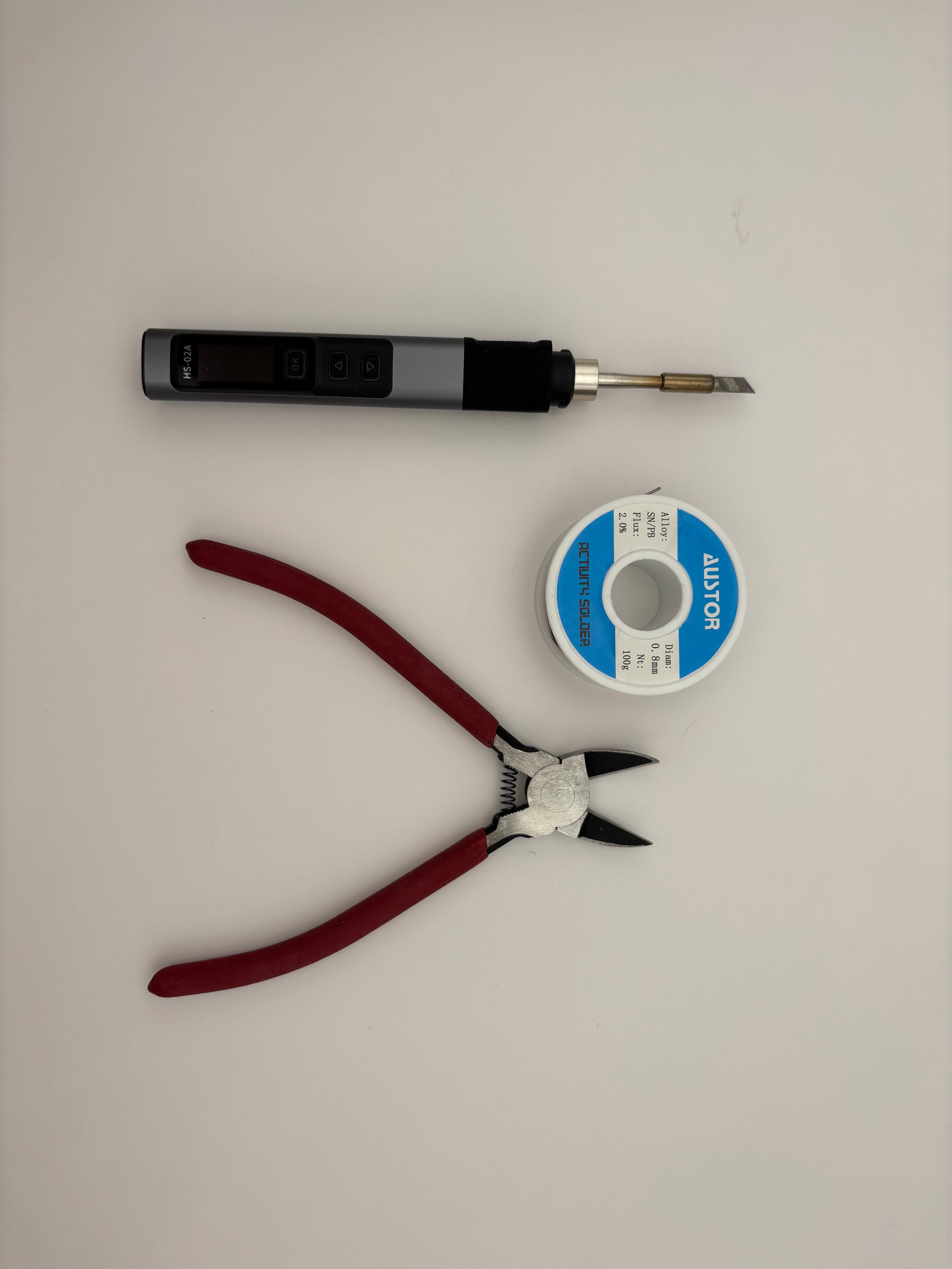
## Tools Needed
* Wire Cutters / Pliers
* Soldering Iron + Solder
 ## Parts Needed
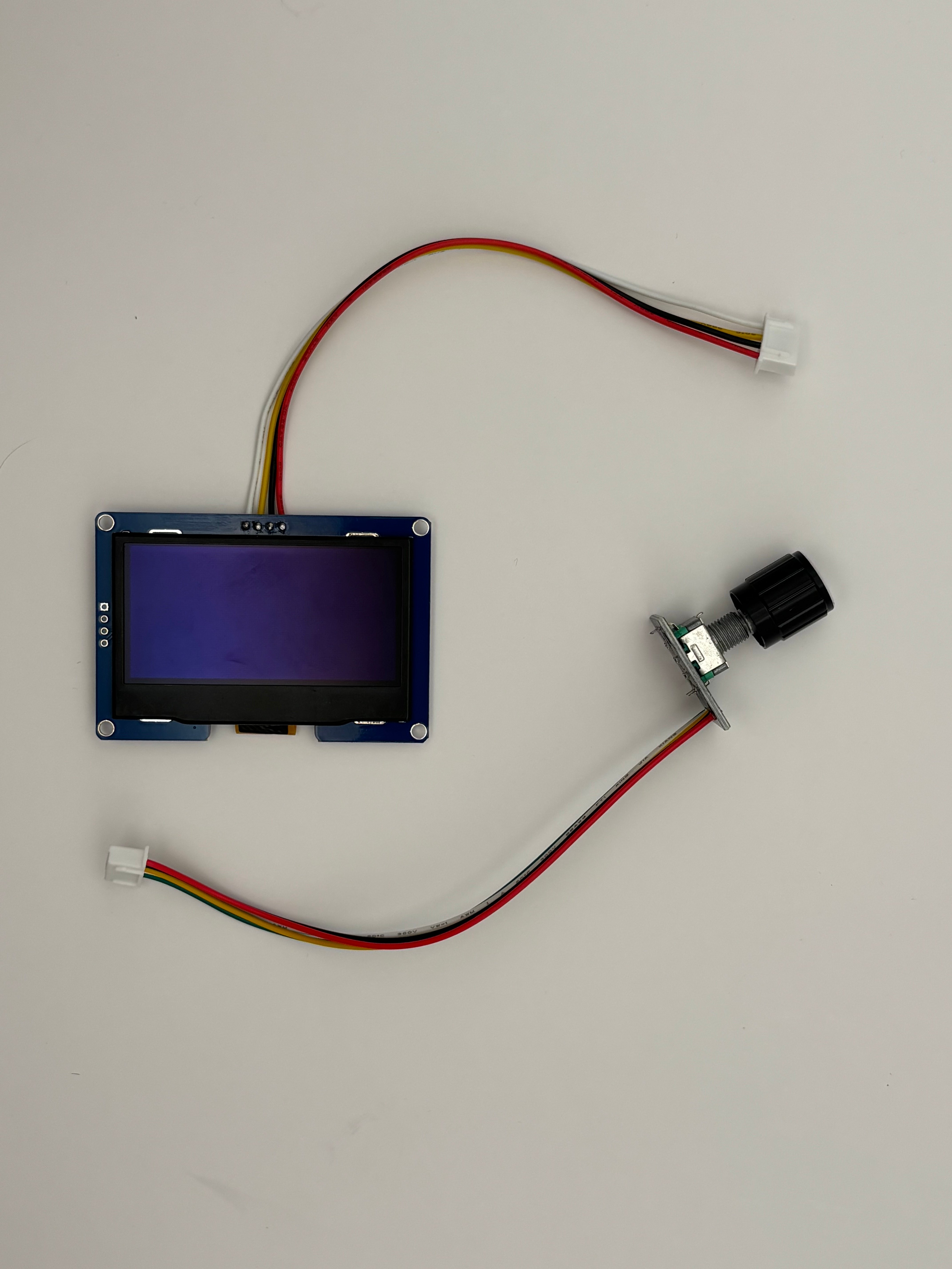
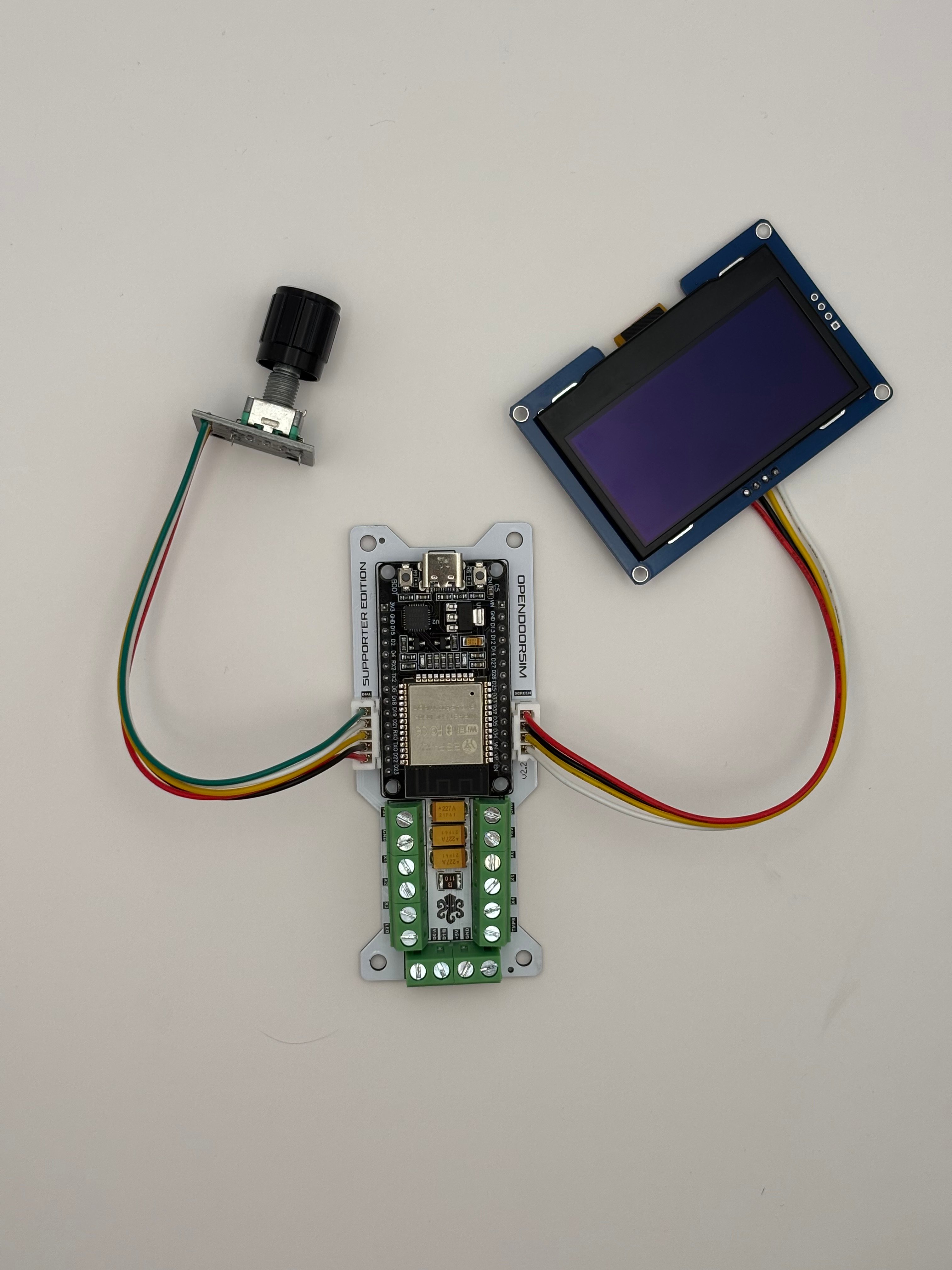
Either from the official kit or self-manufactured.
The kit comes with all parts needed for the following steps.
If you want to double check you have the parts, or don't have a kit, or are self-ordering, check out the Screen and Encoder's [Bill of Materials](/bill-of-materials-lab).
# Build Guide
Ensure you are wiring power and data correctly between your accessories and the ODS board. Because wire harnesses come in many different colors (even in the official kits!), it is unwise to completely rely on the colors you see in the photos below for correct routing.
Use the board, accessories, and wires you have on hand for reference — only you can make sure you are routing them correctly.
Solder the 4 bare end wires of the JST harness into the OLED screen, following the connection table below. Wires should go in from the underside of the screen.
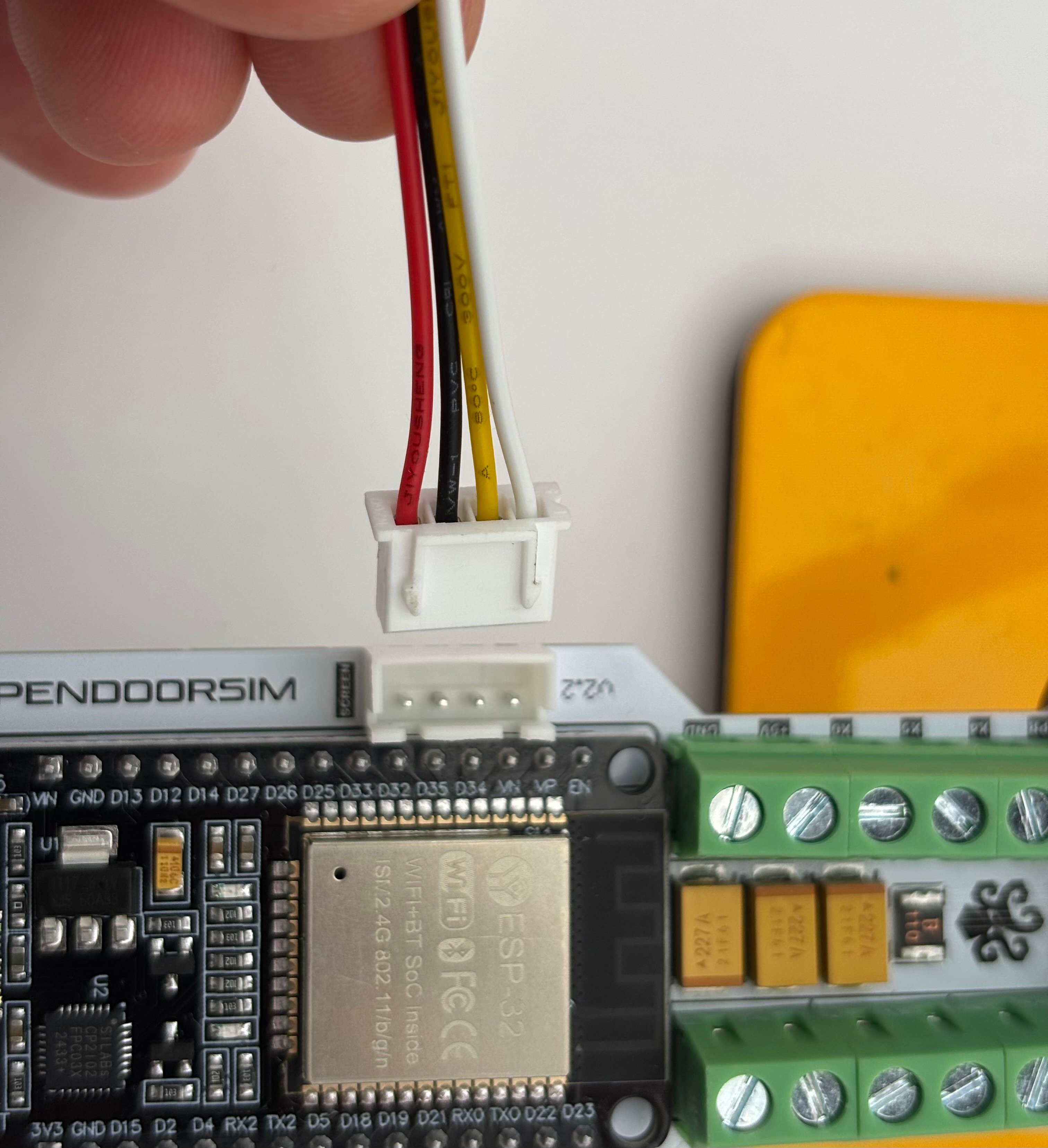
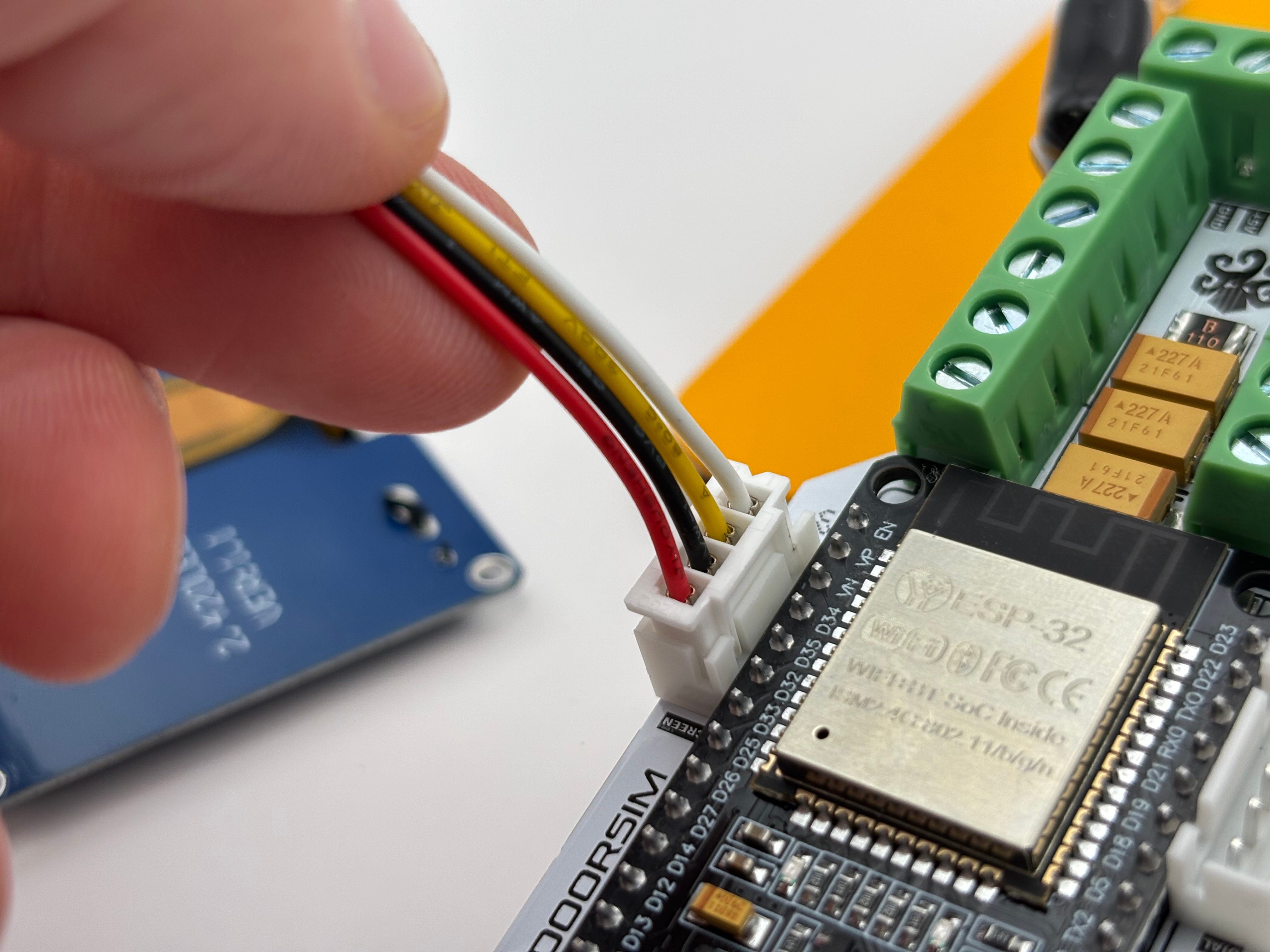
TIP: Plugging the JST connector into the board will allow you to confidently route / solder your wire to the screen. Make sure the four wires are connecting as indicated in the table below:
| ODS BOARD | wire | SCREEN |
| --------- | ---- | ----------------- |
| GND | ←→ | GND |
| +3V | ←→ | VDD / VCC / POWER |
| SCL | ←→ | SCL |
| SDA | ←→ | SDA |
## Parts Needed
Either from the official kit or self-manufactured.
The kit comes with all parts needed for the following steps.
If you want to double check you have the parts, or don't have a kit, or are self-ordering, check out the Screen and Encoder's [Bill of Materials](/bill-of-materials-lab).
# Build Guide
Ensure you are wiring power and data correctly between your accessories and the ODS board. Because wire harnesses come in many different colors (even in the official kits!), it is unwise to completely rely on the colors you see in the photos below for correct routing.
Use the board, accessories, and wires you have on hand for reference — only you can make sure you are routing them correctly.
Solder the 4 bare end wires of the JST harness into the OLED screen, following the connection table below. Wires should go in from the underside of the screen.
TIP: Plugging the JST connector into the board will allow you to confidently route / solder your wire to the screen. Make sure the four wires are connecting as indicated in the table below:
| ODS BOARD | wire | SCREEN |
| --------- | ---- | ----------------- |
| GND | ←→ | GND |
| +3V | ←→ | VDD / VCC / POWER |
| SCL | ←→ | SCL |
| SDA | ←→ | SDA |
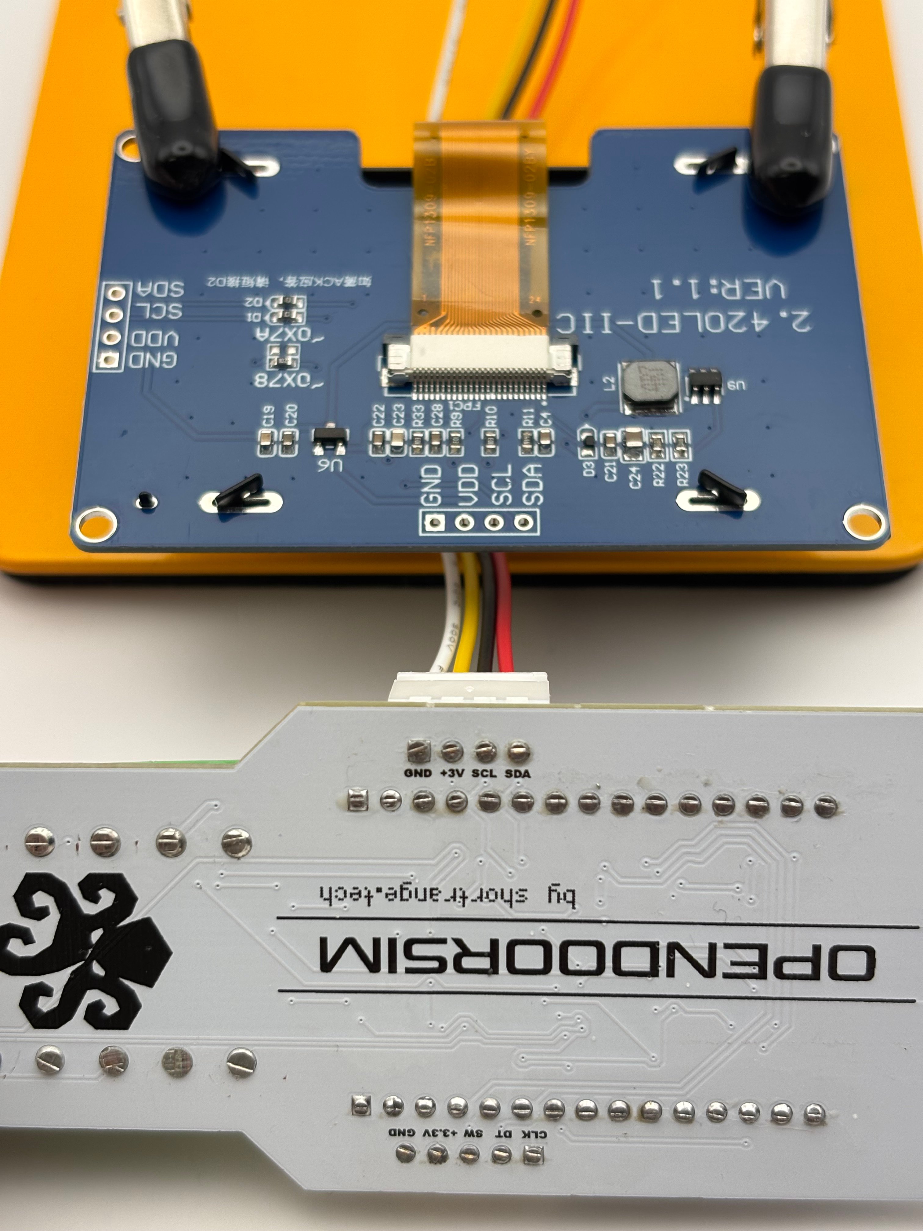
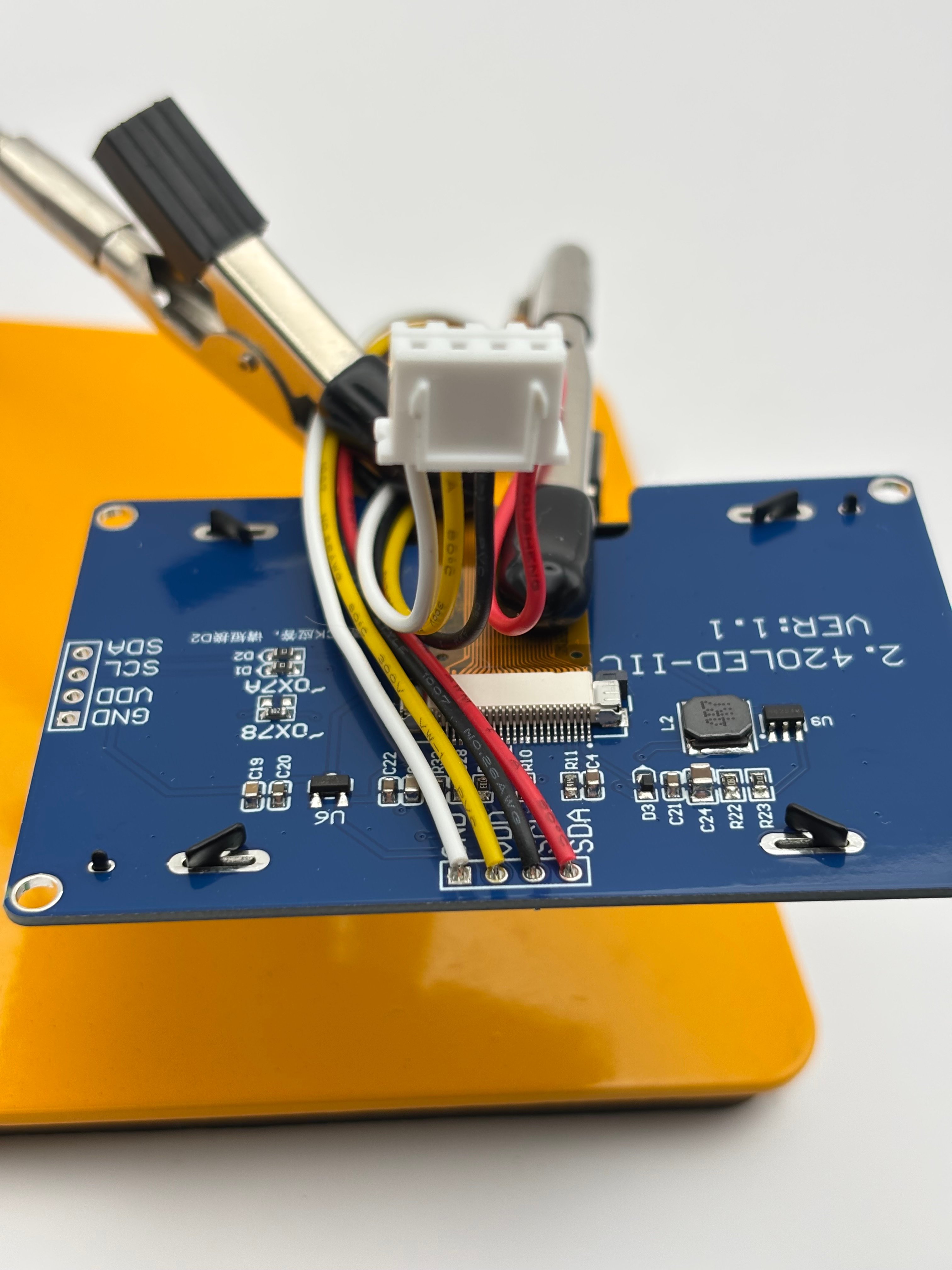
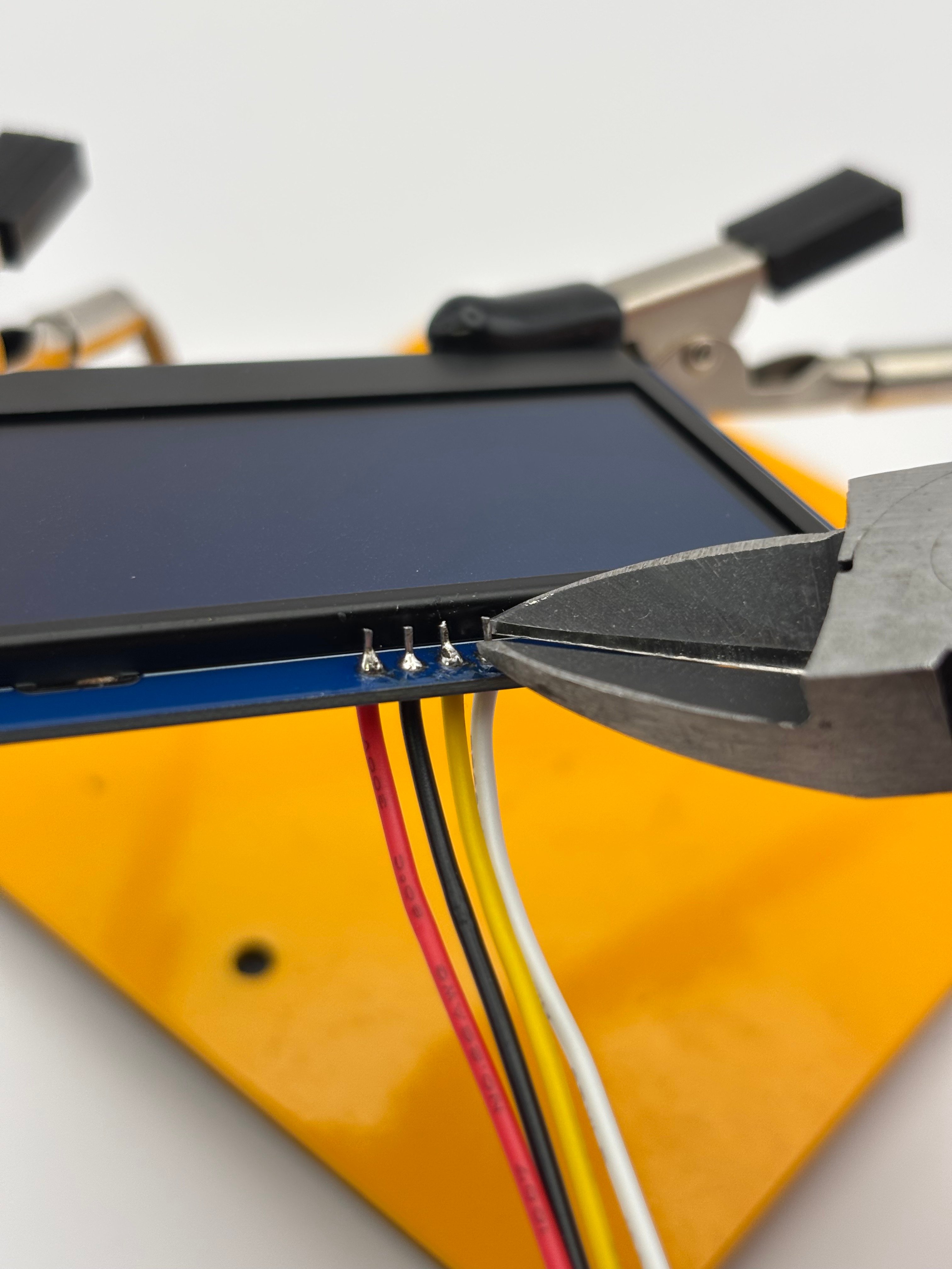 Ensure wire routing for the screen is correct, double checking with the table above.
 If your encoder includes pin headers, they must be removed.
First, bend the encoder pins straight(ish) so they are easier to remove, using pliers or cutters of your choice.
Next, heat each pin with a soldering iron, and use pliers / cutters to gently grip, wiggle, and pull them out one by one.
If your encoder includes pin headers, they must be removed.
First, bend the encoder pins straight(ish) so they are easier to remove, using pliers or cutters of your choice.
Next, heat each pin with a soldering iron, and use pliers / cutters to gently grip, wiggle, and pull them out one by one.
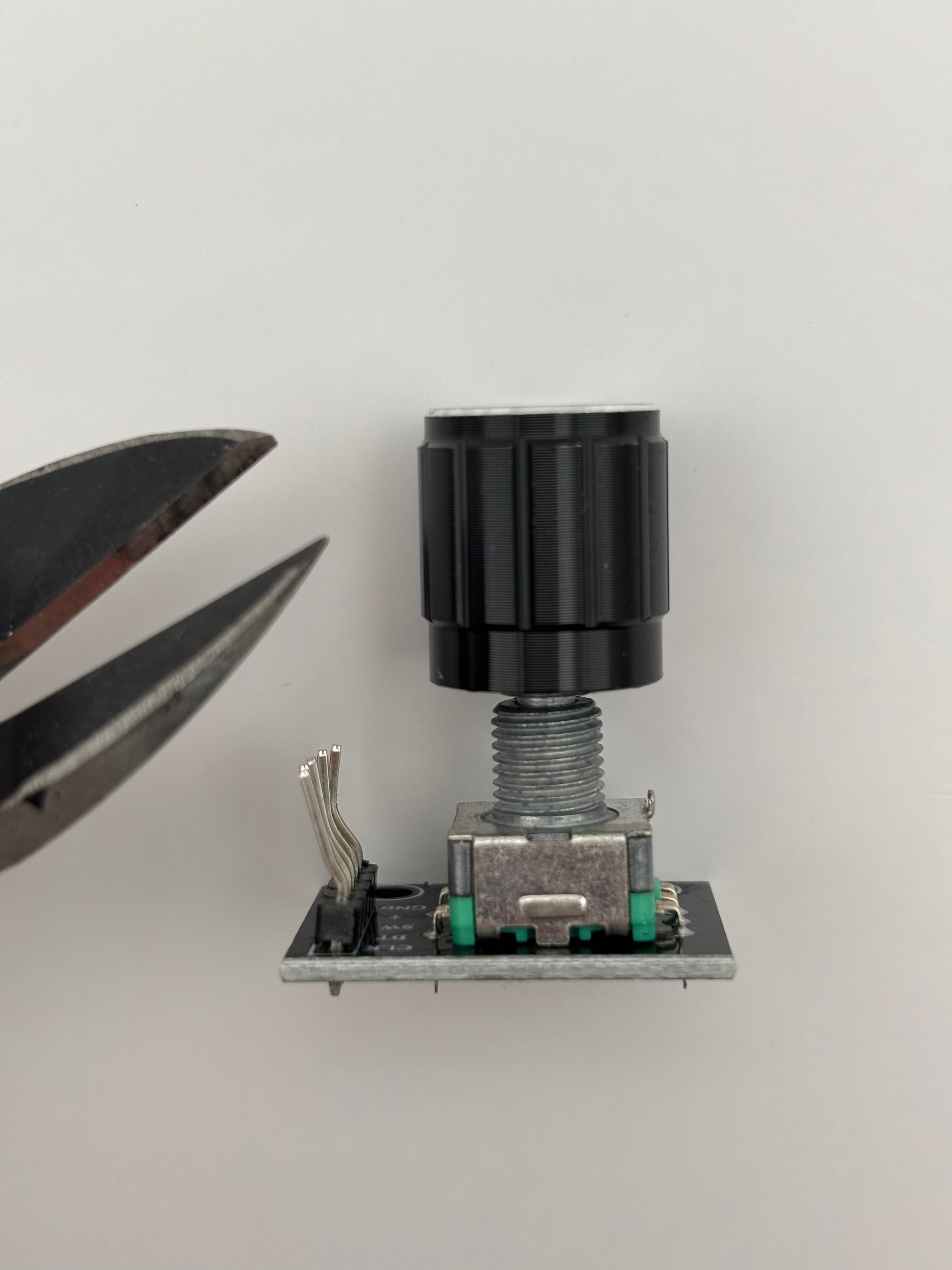
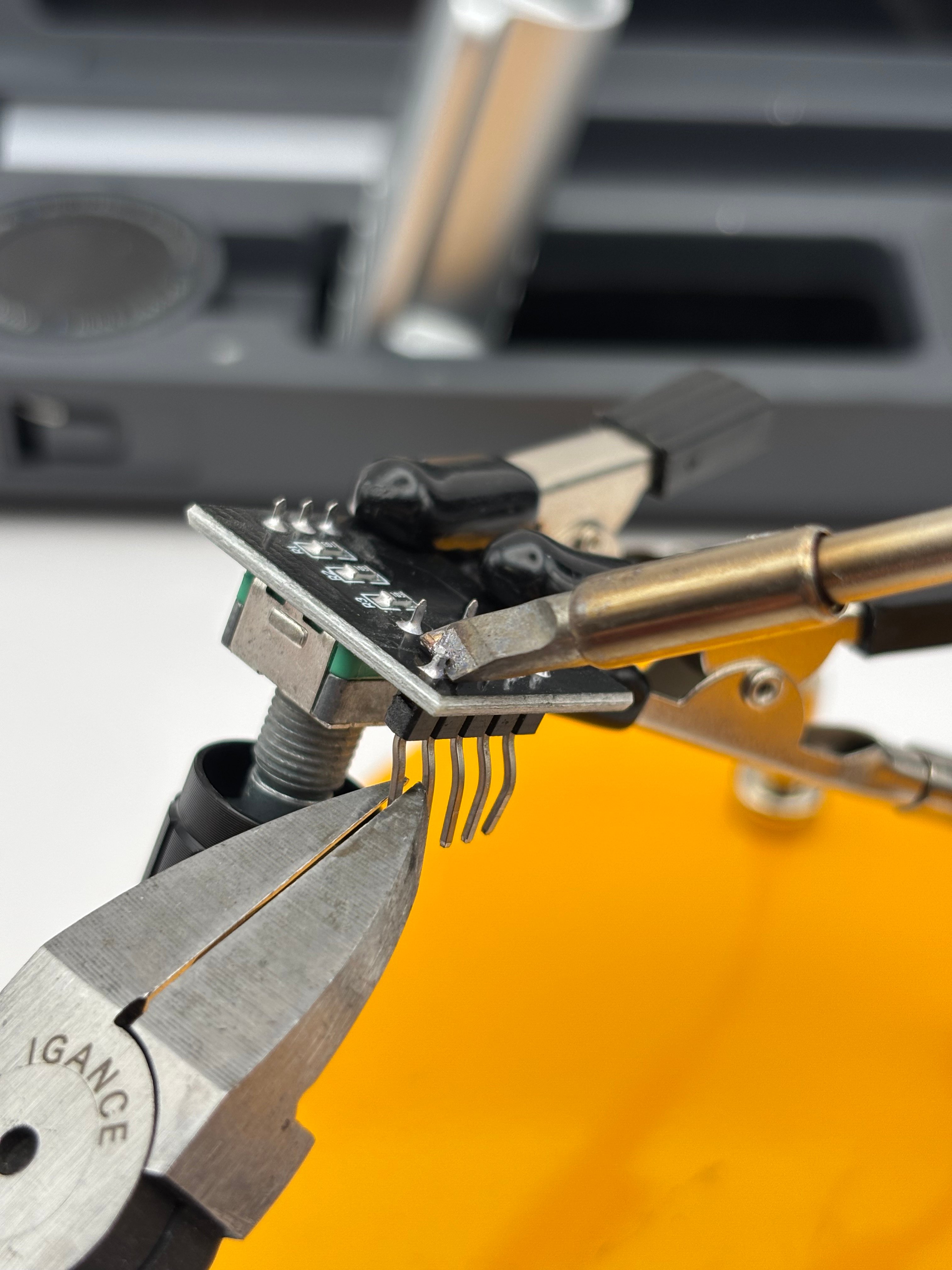
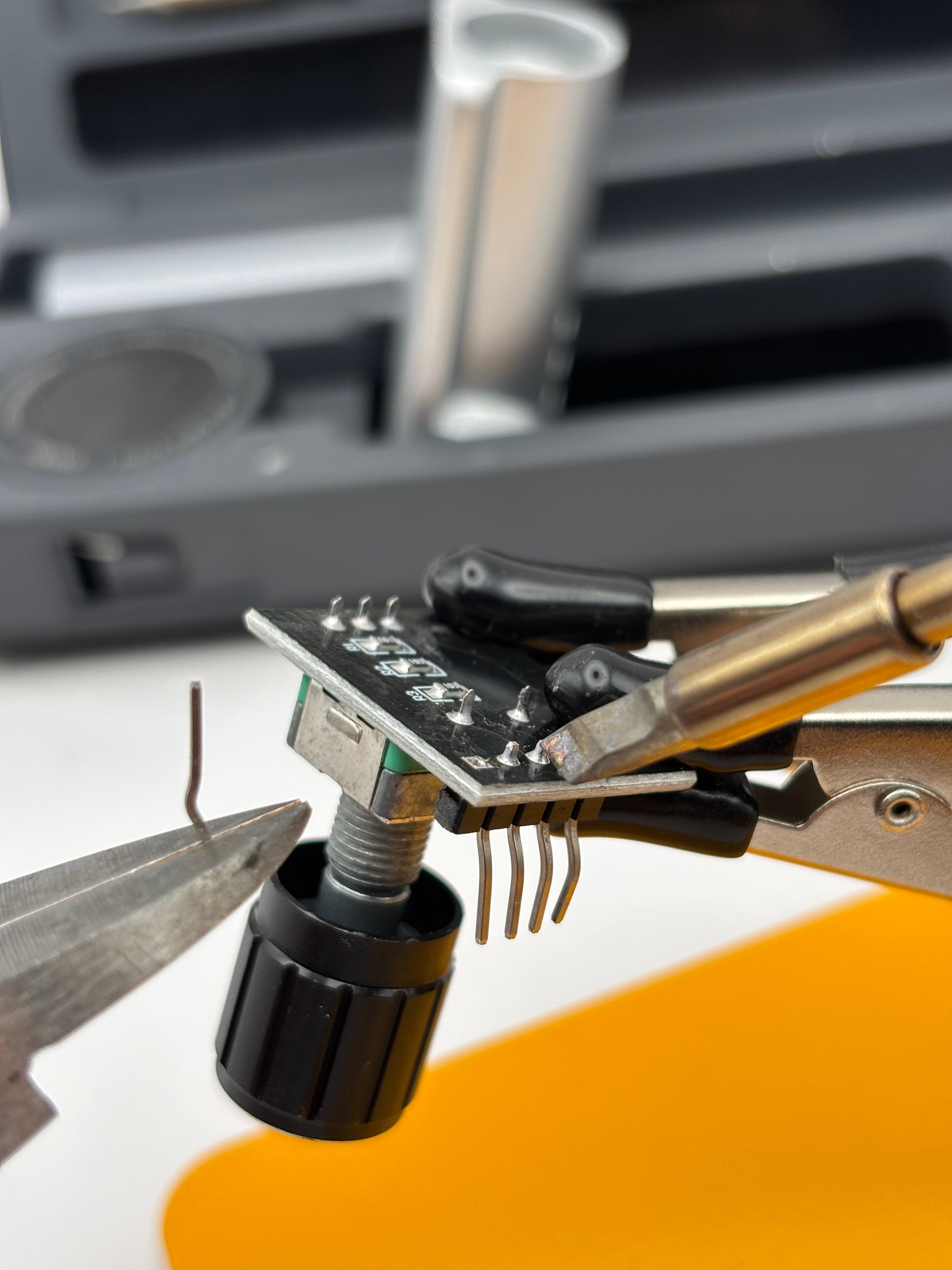 After removing, some solder may remain, but the pins and plastic pin header should be gone to make room for the wires.
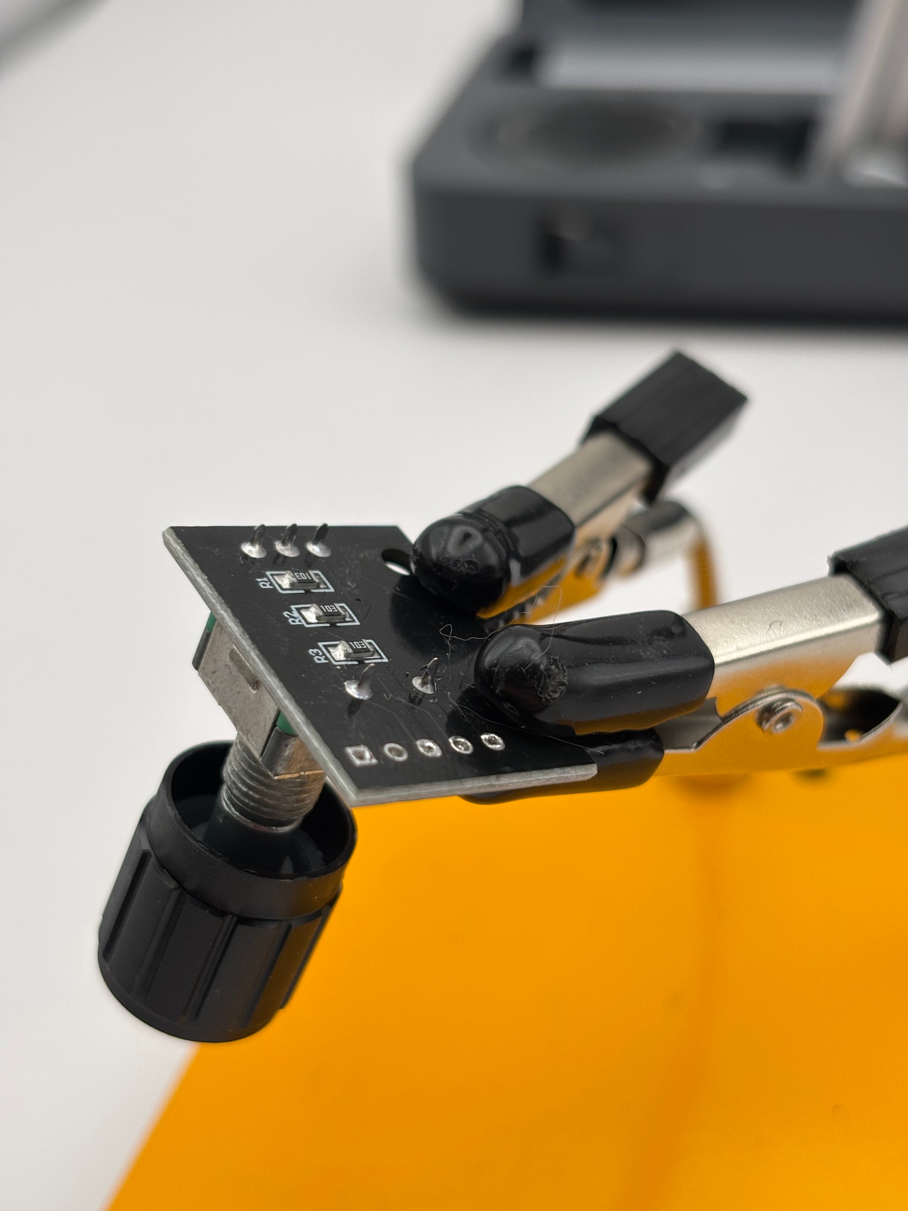 Solder the 5 bare end wires of the JST harness into the encoder, following the connection table below. Wires should go in from the underside of the encoder.
TIP: Plugging the JST connector into the board will allow you to confidently route / solder your wire to the screen. Make sure the four wires are connecting as indicated in the table below:
| ODS BOARD | wire | ENCODER |
| ----------- | ---- | ------- |
| CLK | ←→ | CLK |
| DT | ←→ | DT |
| SW | ←→ | SW |
| +3.3V / +3V | ←→ | + |
| GND | ←→ | GND |
Solder the 5 bare end wires of the JST harness into the encoder, following the connection table below. Wires should go in from the underside of the encoder.
TIP: Plugging the JST connector into the board will allow you to confidently route / solder your wire to the screen. Make sure the four wires are connecting as indicated in the table below:
| ODS BOARD | wire | ENCODER |
| ----------- | ---- | ------- |
| CLK | ←→ | CLK |
| DT | ←→ | DT |
| SW | ←→ | SW |
| +3.3V / +3V | ←→ | + |
| GND | ←→ | GND |
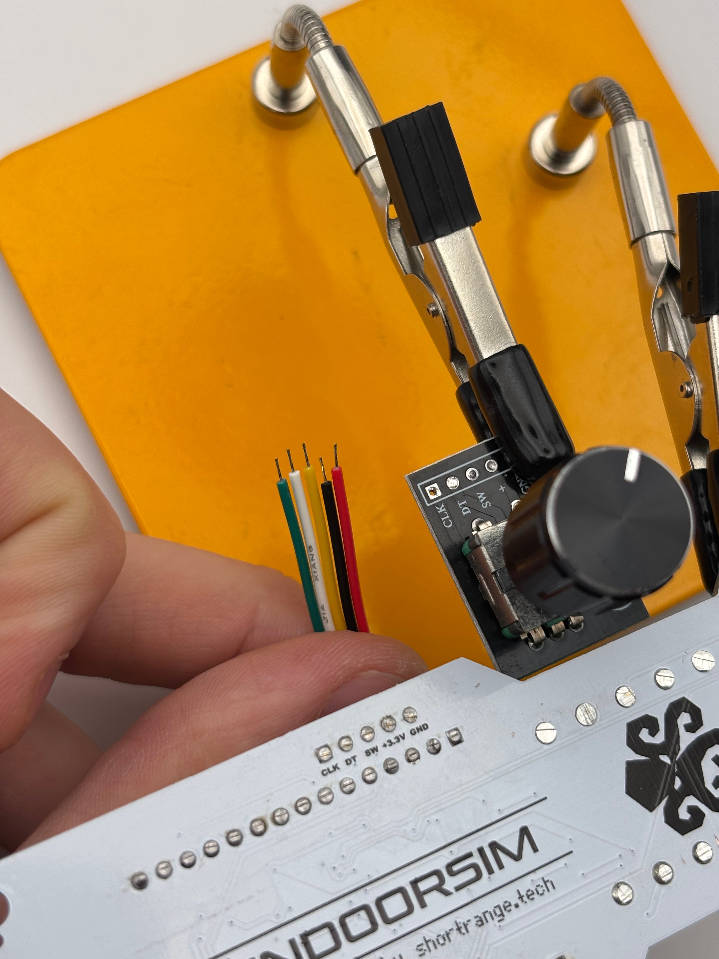
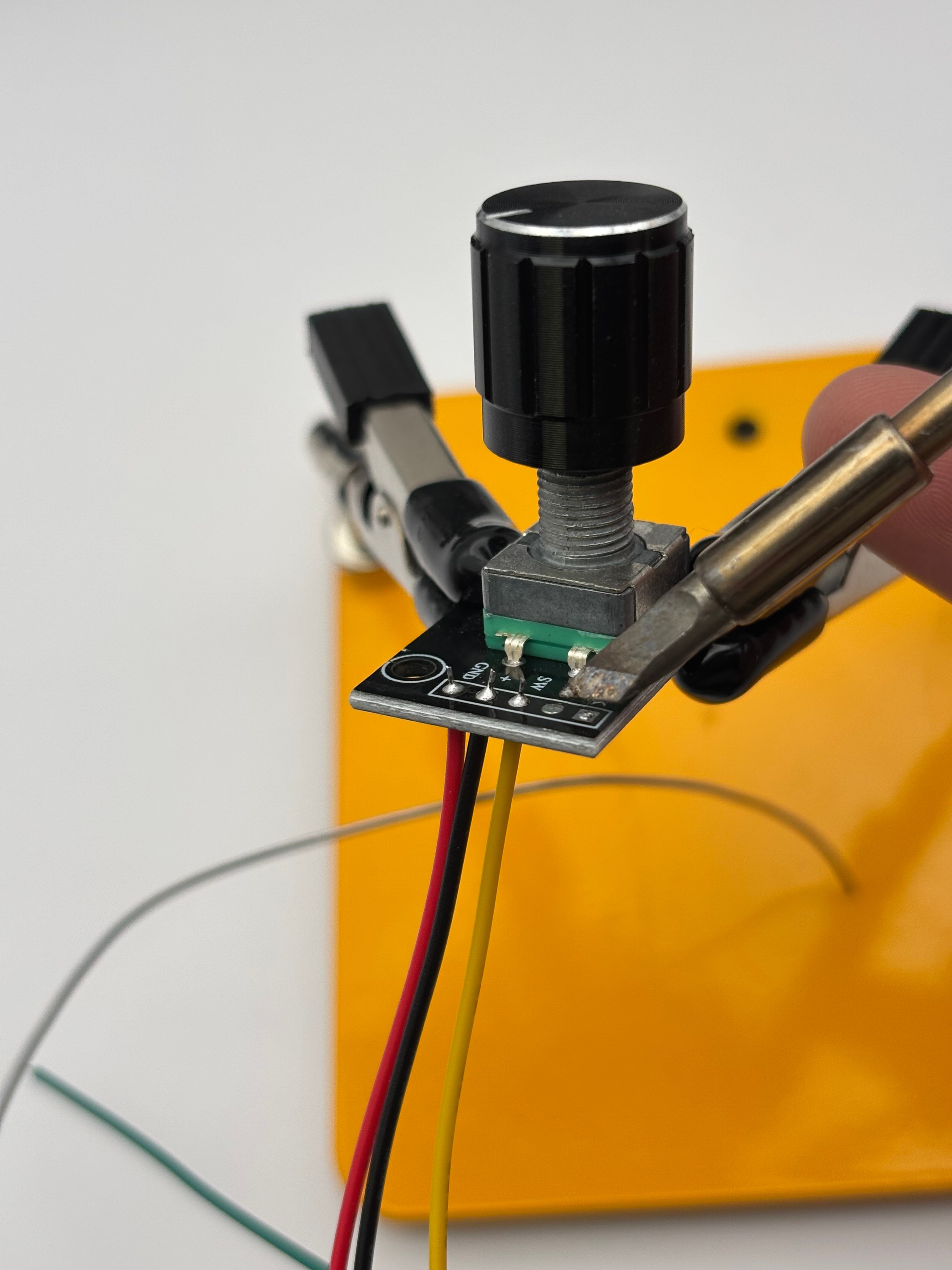
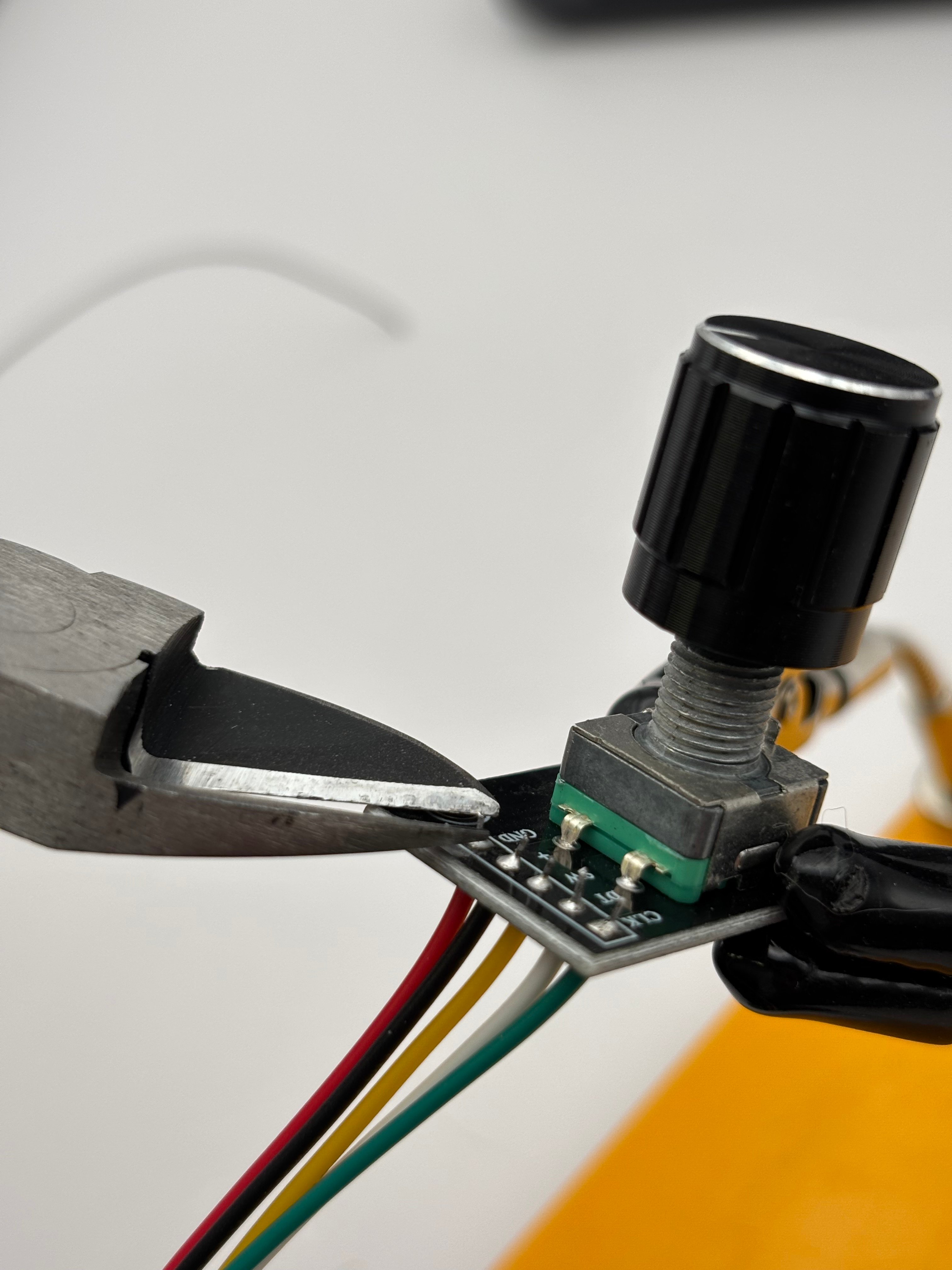 Ensure wire routing for the encoder is correct, double checking with the table above.
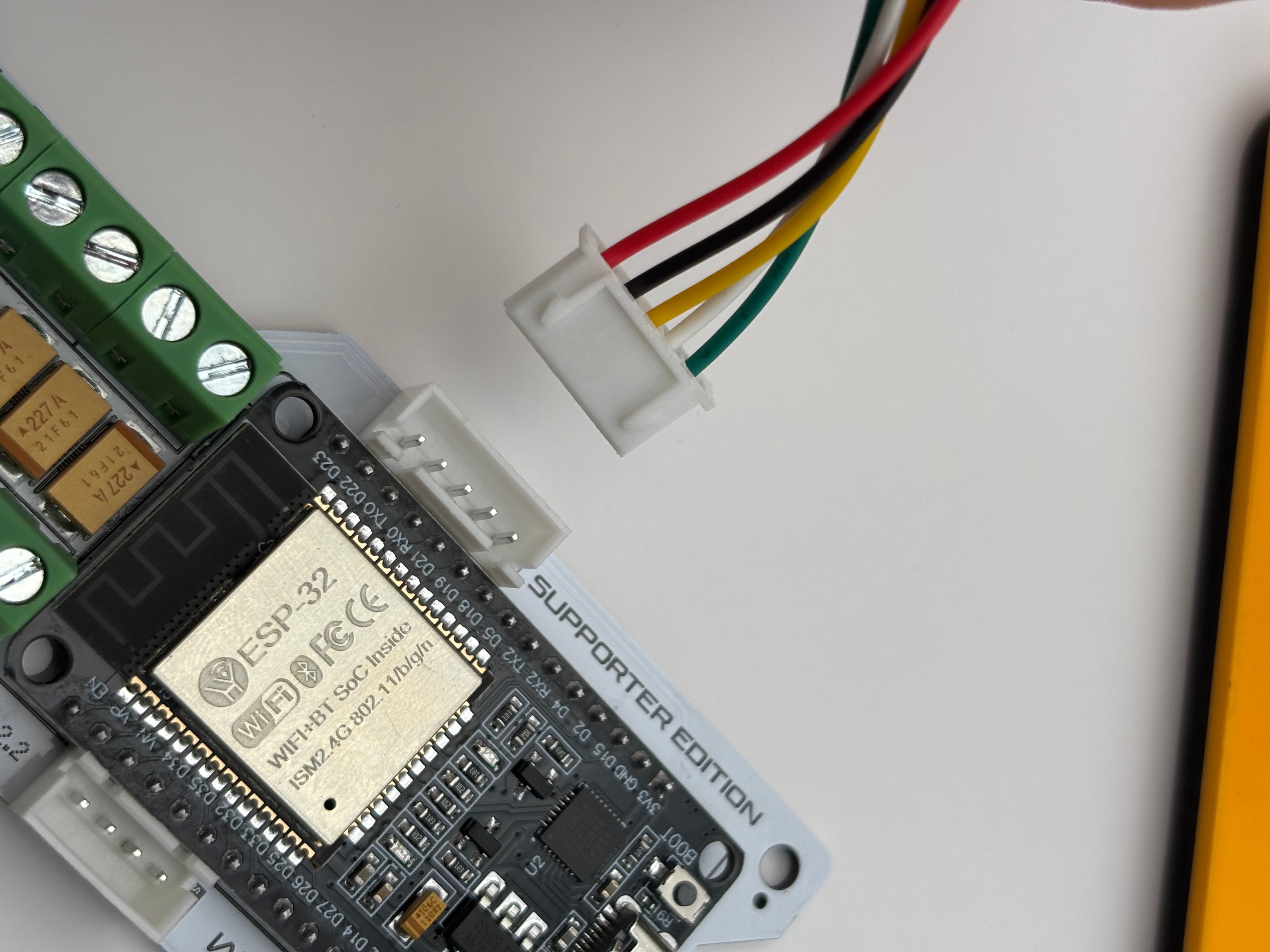
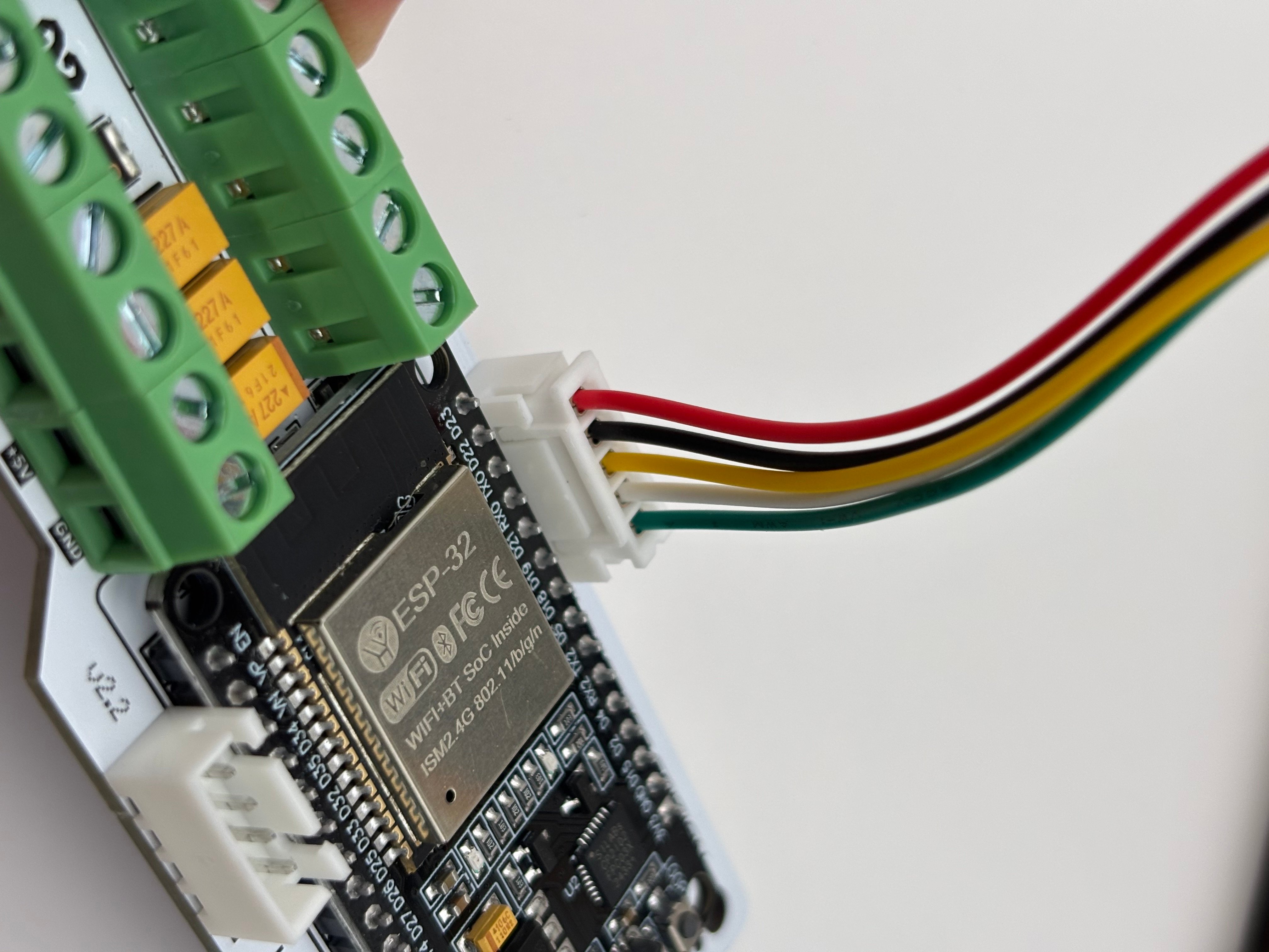 Ensure that all wires are correctly routed, matching the routing tables above.
Now, power the board with USB-C. If the board is flashed, the screen should light up, and the encoder should trigger the menu when clicked and rotated!
Ensure that all wires are correctly routed, matching the routing tables above.
Now, power the board with USB-C. If the board is flashed, the screen should light up, and the encoder should trigger the menu when clicked and rotated!