> ## Documentation Index
> Fetch the complete documentation index at: https://docs.shortrange.tech/llms.txt
> Use this file to discover all available pages before exploring further.

# LAB Case Build Guide

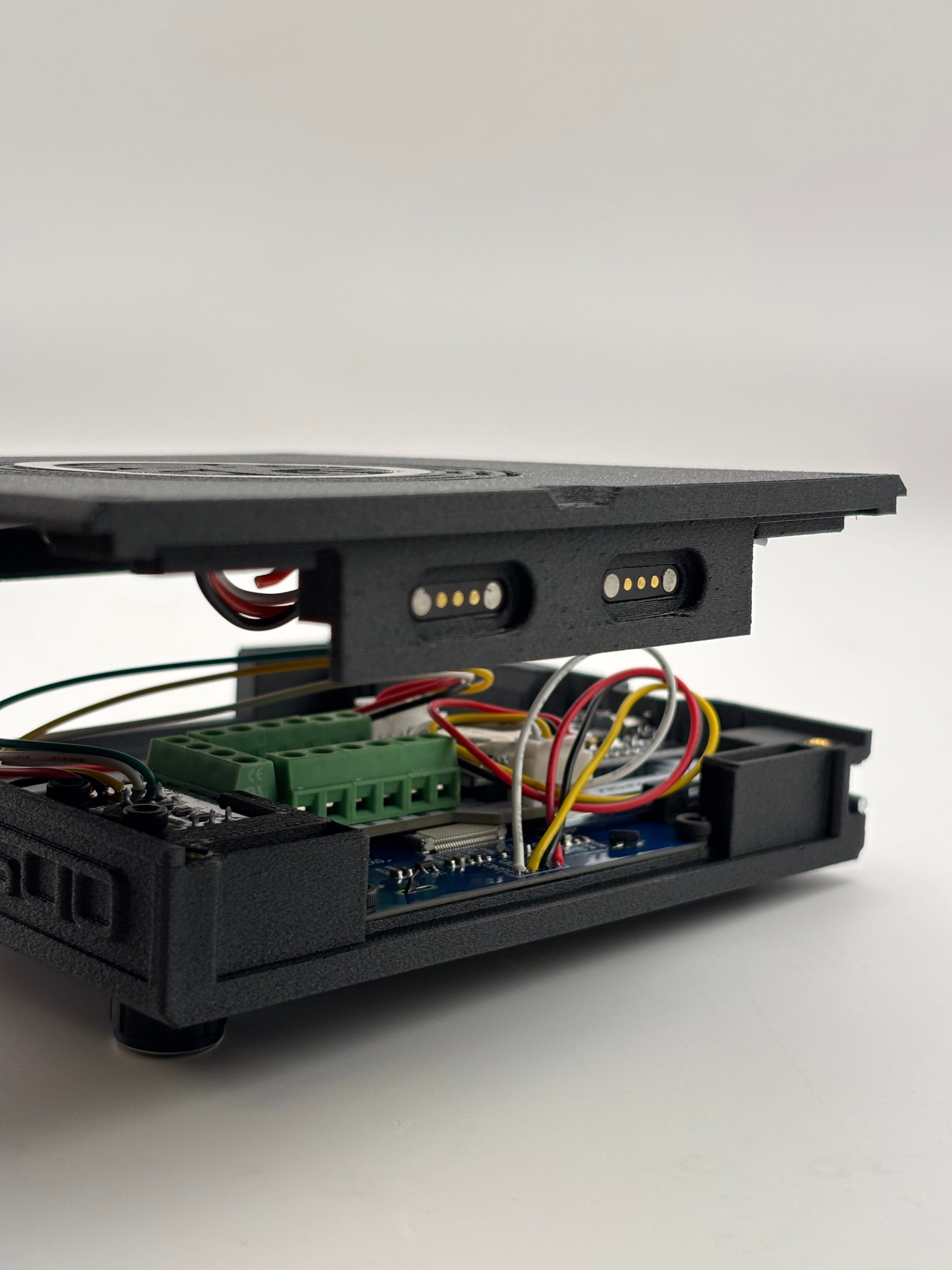
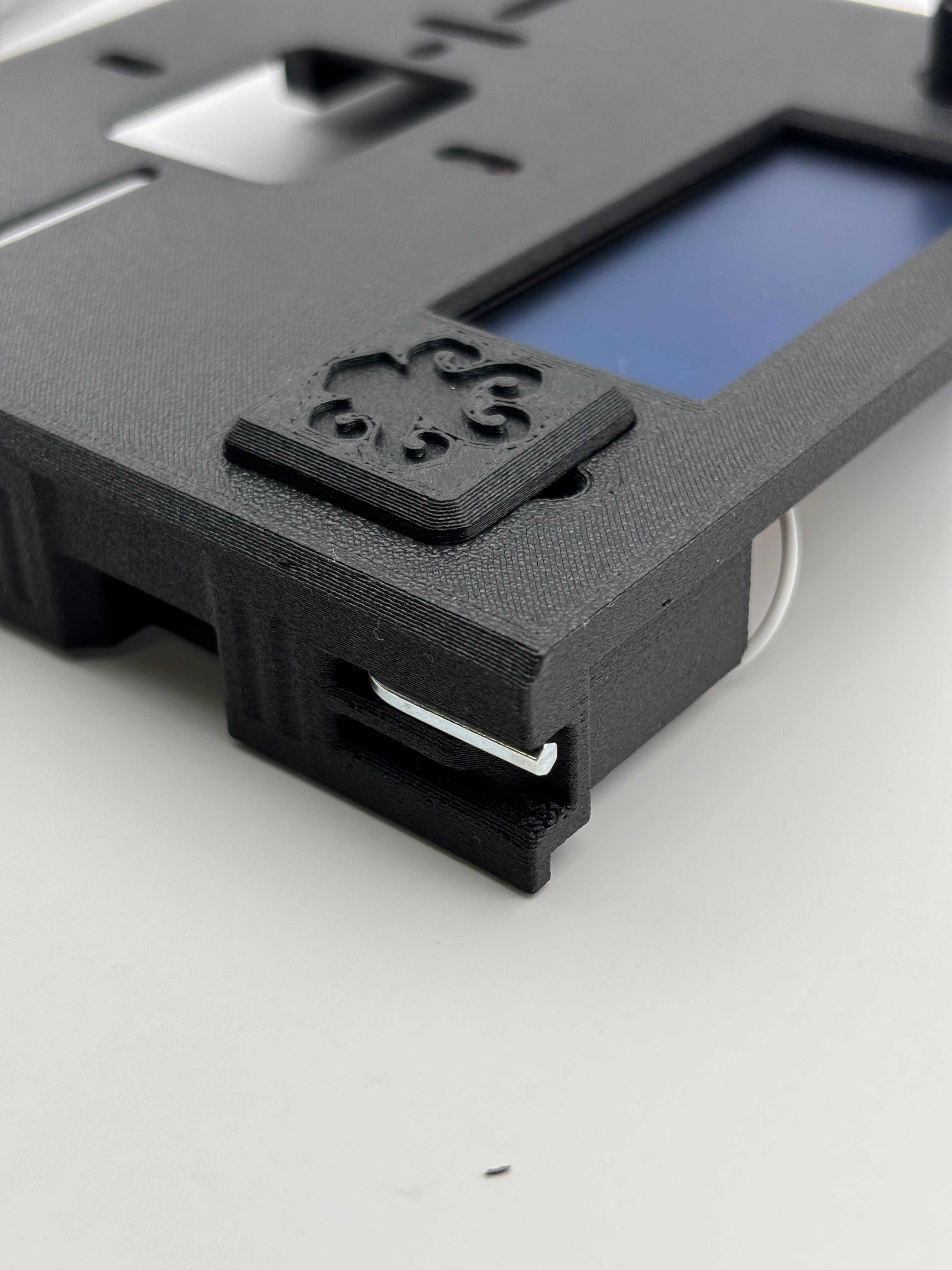
It's time to enclose your ODS board, screen, and encoder in an rugged case that includes a mount for your reader and more.

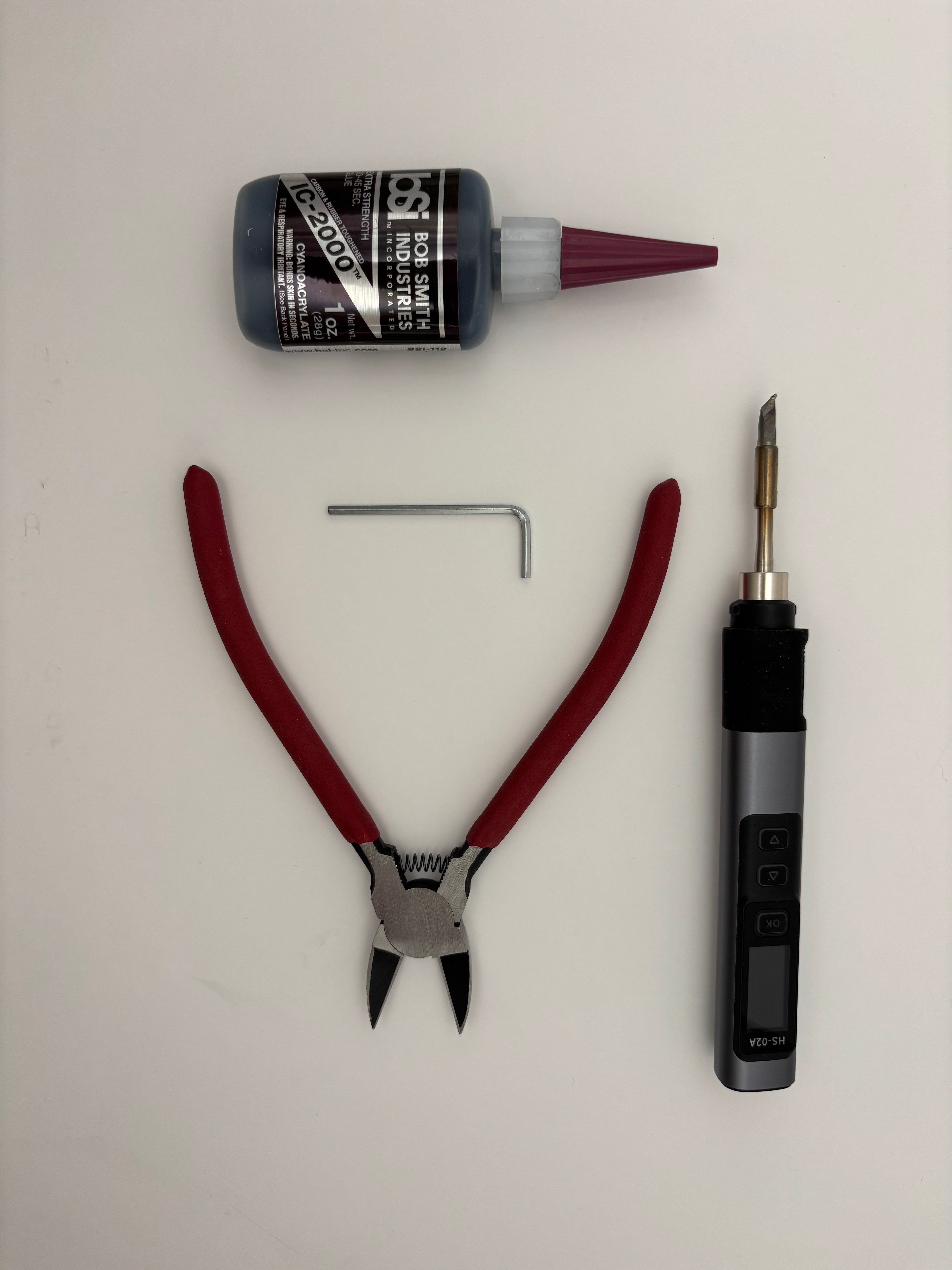
## Tools Needed

<Columns cols={2}>
  <Column>
    * Wire Cutters
    * Soldering Iron + Solder
    * 2.5mm Allen Key
    * Industrial Superglue
  </Column>

  <Column>
    <Frame>
      <img src="https://mintcdn.com/shortrangetechnologies/mlzaVSup-lfTqw-5/images/IMG_5914.jpeg?fit=max&auto=format&n=mlzaVSup-lfTqw-5&q=85&s=638849d0ff37883c675ea9f63c443619" alt="IMG 5914" width="5712" height="4284" data-path="images/IMG_5914.jpeg" />
    </Frame>
  </Column>
</Columns>

## Parts Needed

<Card title="Pre-Built OpenDoorSim Board" icon="binary">
  Either from the official kit or self-manufactured.
</Card>

<Card title="Built Screen and Encoder" icon="tv">
  Using parts from the kit or self ordered, and built following the [previous build guide](/opendoorsim/build-guides/screen-and-encoder).
</Card>

<Card title="LAB Kit Case Parts" icon="box-alt">
  The kit comes with all parts needed for the following steps.

  If you want to double check you have the parts, or don't have a kit, or are self-ordering, check out the Lab Case's [Bill of Materials](/bill-of-materials-lab).
</Card>

# Build Guide

<Steps>
  <Step title="STEP ONE: MAGNETS" icon="magnet" titleSize="h2">
    <Note>
      **Official kits come with the decal tile already assembled.**
    </Note>

    <Warning>
      Avoid snapping magnets together as they may break from impact.
    </Warning>

    <Steps>
      <Step title="Install Decal Tile Magnet" titleSize="h3">
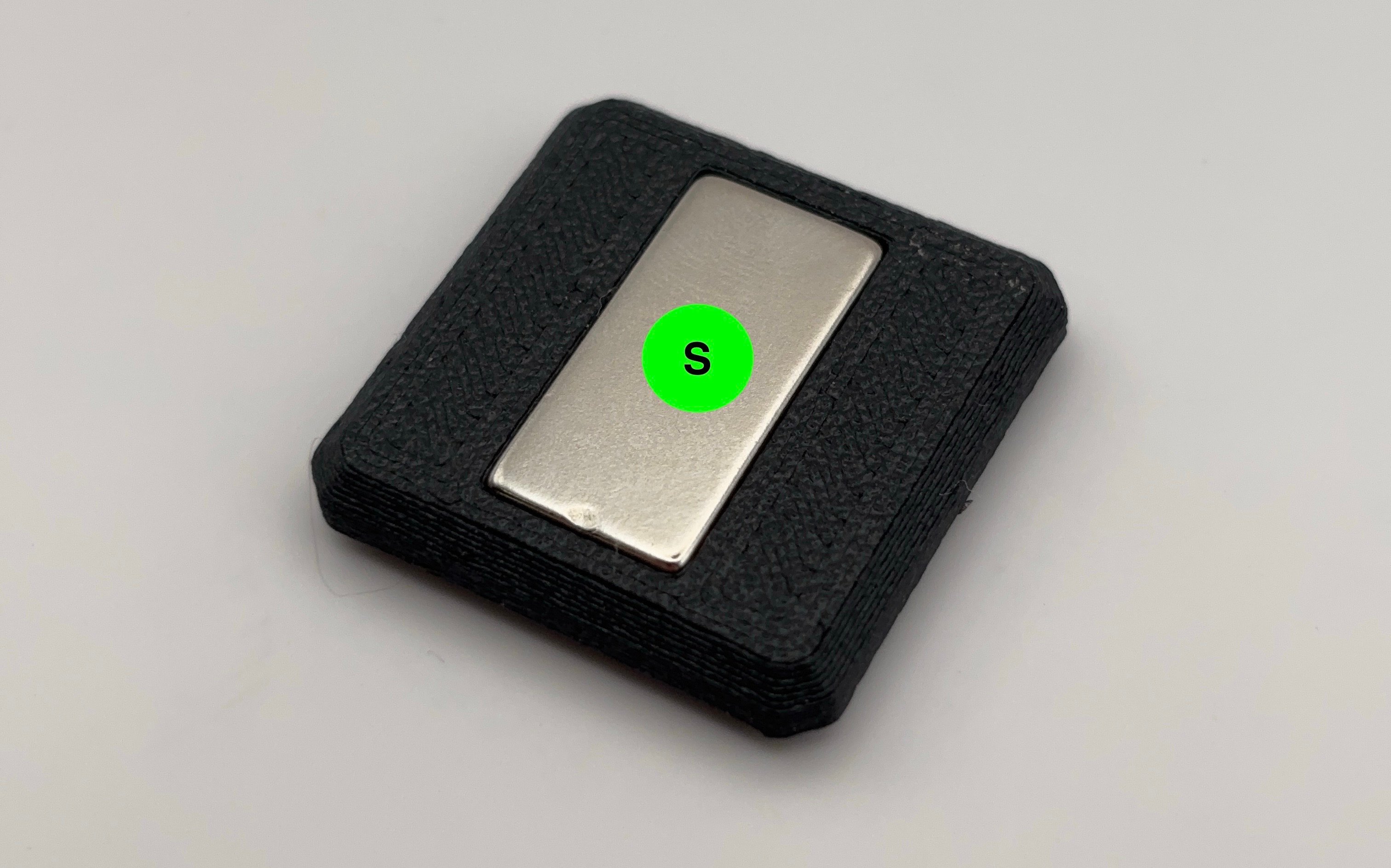
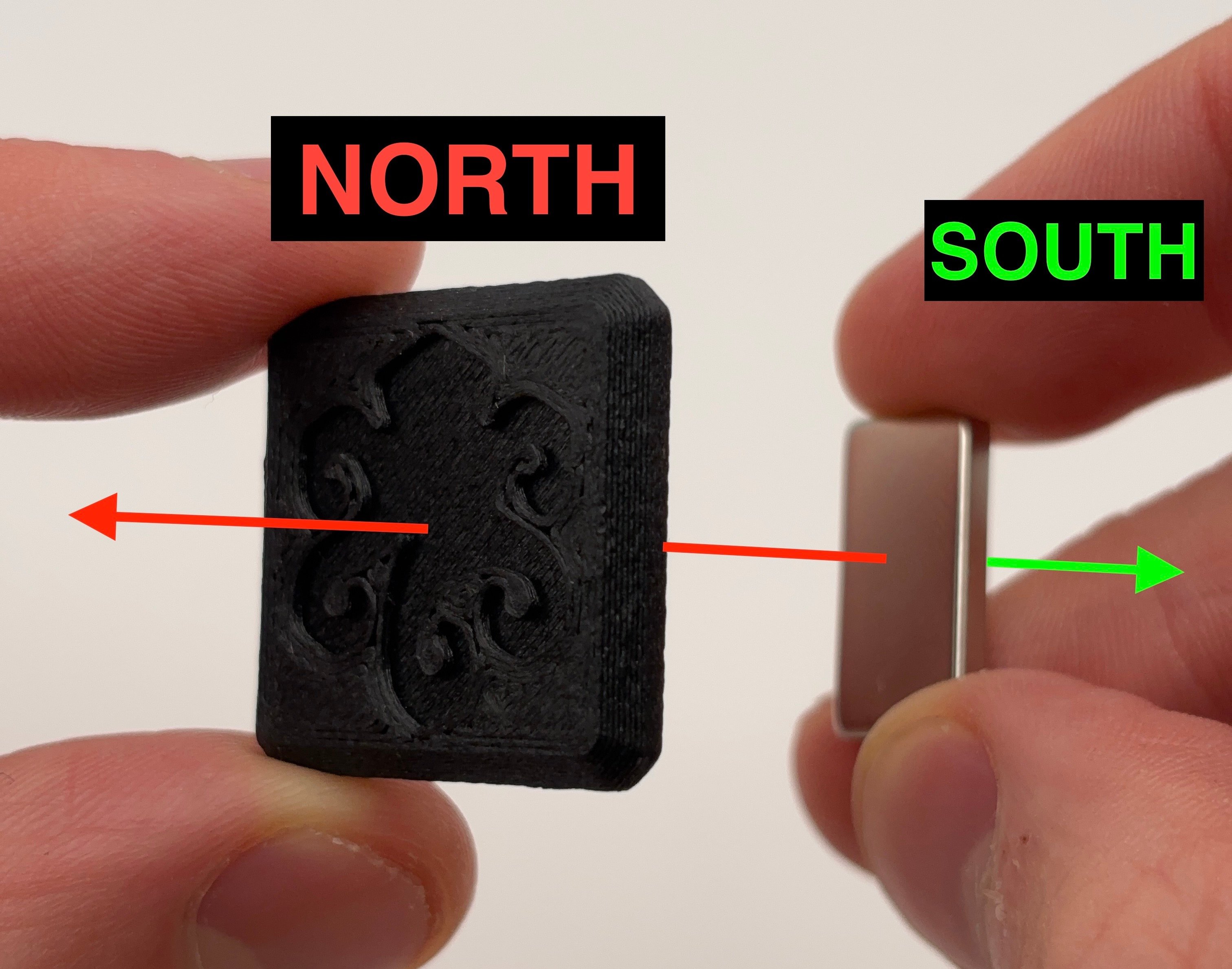
        Insert 1x thin magnet (20x10x3) into the decal tile.

        **<u>North</u>** side should face in and towards the logo.

        Once inserted, only the **<u>south</u>** face of the magnet should be visible.
        <Frame>
          <img src="https://mintcdn.com/shortrangetechnologies/mzmpgnwUEJeXwaLI/images/IMG_5976.jpeg?fit=max&auto=format&n=mzmpgnwUEJeXwaLI&q=85&s=0d5907e1fdb0cc063f3824eef7d94087" alt="IMG 5976" title="IMG 5976" className="mx-auto" style={{ width:"67%" }} width="3024" height="2379" data-path="images/IMG_5976.jpeg" />
        </Frame>

        <Frame>
          <img src="https://mintcdn.com/shortrangetechnologies/mzmpgnwUEJeXwaLI/images/IMG_5953-1.jpeg?fit=max&auto=format&n=mzmpgnwUEJeXwaLI&q=85&s=38b3ed07f94e0216ed83e9d3b5559eb5" alt="IMG 5953 1" title="IMG 5953 1" className="mx-auto" style={{ width:"67%" }} width="3024" height="1886" data-path="images/IMG_5953-1.jpeg" />
        </Frame>
      </Step>

      <Step title="Install Decal Tile Mount Magnet" titleSize="h3">
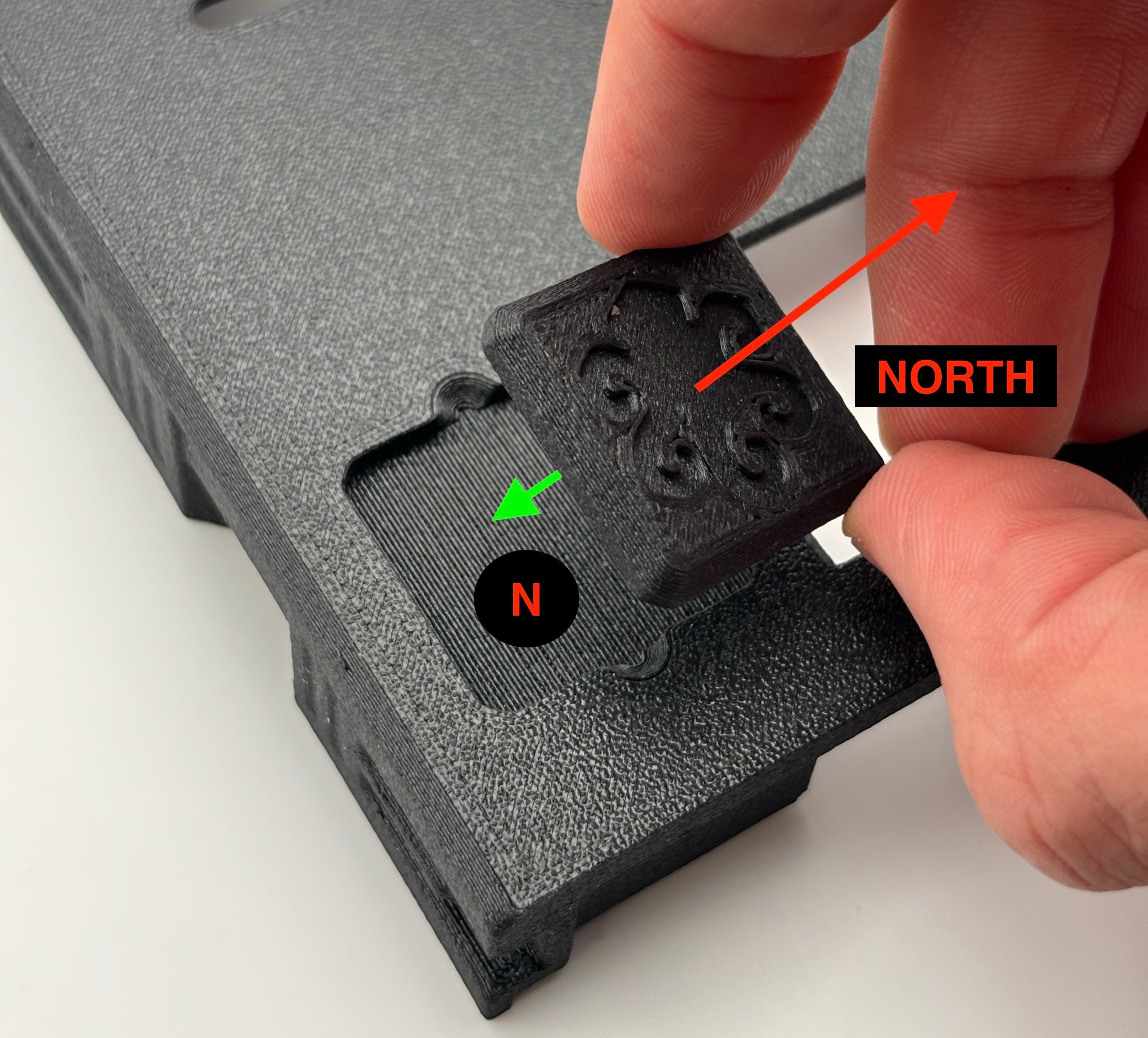
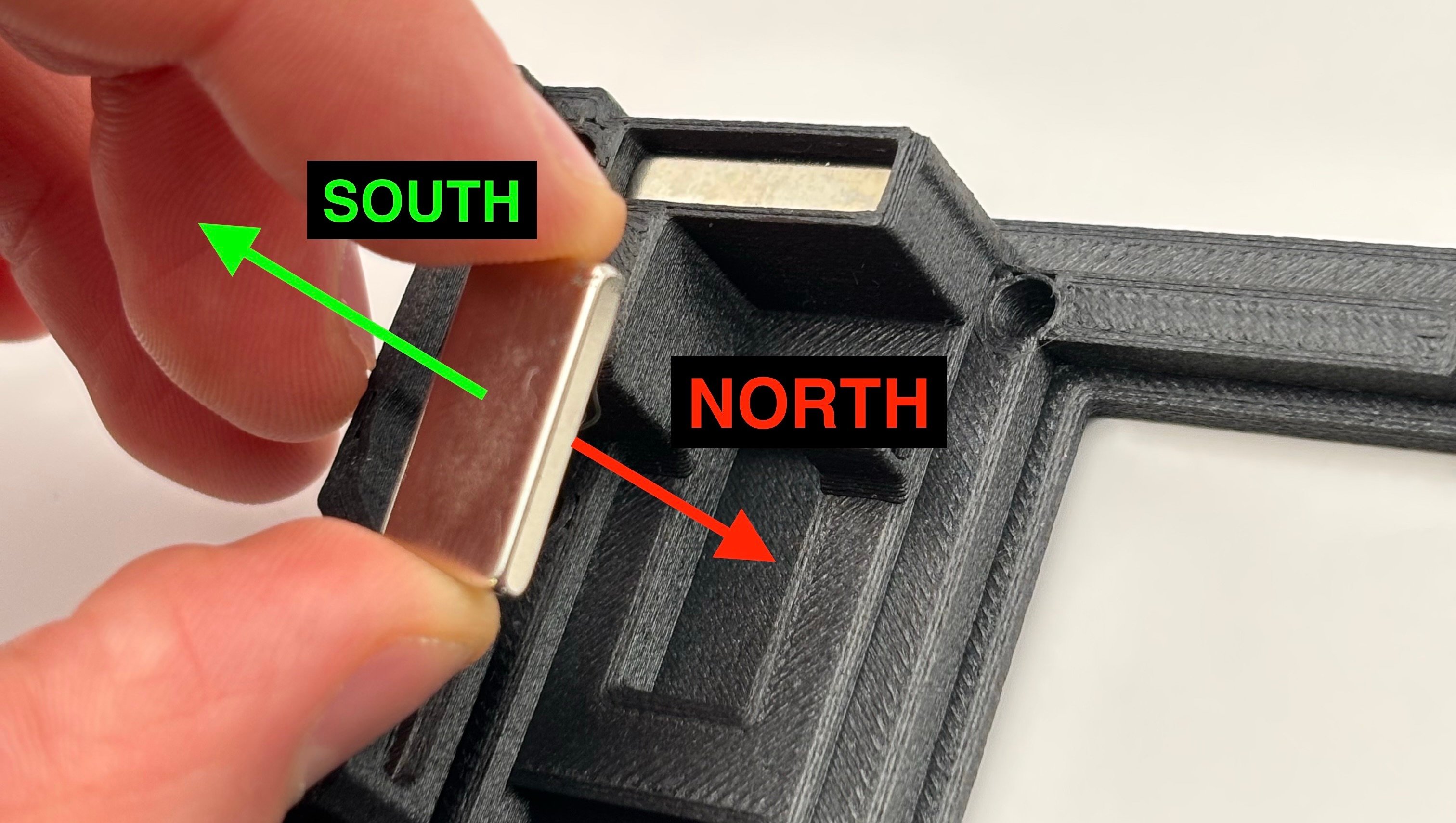
        Insert 1x thin magnet (20x10x3) into the case body for the decal tile mount.

        **<u>North</u>** side of the magnet should face out and away from the case. This magnet serves to snap the decal tile to the case.

        Once inserted, the decal tile should snap to the case!
        <Frame>
          <img src="https://mintcdn.com/shortrangetechnologies/ffhwWTE-aanwS6N_/images/IMG_6021.jpeg?fit=max&auto=format&n=ffhwWTE-aanwS6N_&q=85&s=afaa187f44f5dbc3048329ef7e365405" alt="IMG 6021" title="IMG 6021" className="mx-auto" style={{ width:"67%" }} width="3024" height="1709" data-path="images/IMG_6021.jpeg" />
        </Frame>

        <Frame>
          <img src="https://mintcdn.com/shortrangetechnologies/ffhwWTE-aanwS6N_/images/IMG_6023.jpeg?fit=max&auto=format&n=ffhwWTE-aanwS6N_&q=85&s=8967573fe3feefe4f711fbc17565c818" alt="IMG 6023" title="IMG 6023" className="mx-auto" style={{ width:"67%" }} width="3024" height="2735" data-path="images/IMG_6023.jpeg" />
        </Frame>
      </Step>

      <Step title="Install Module / End Cap Mount Magnets" titleSize="h3">
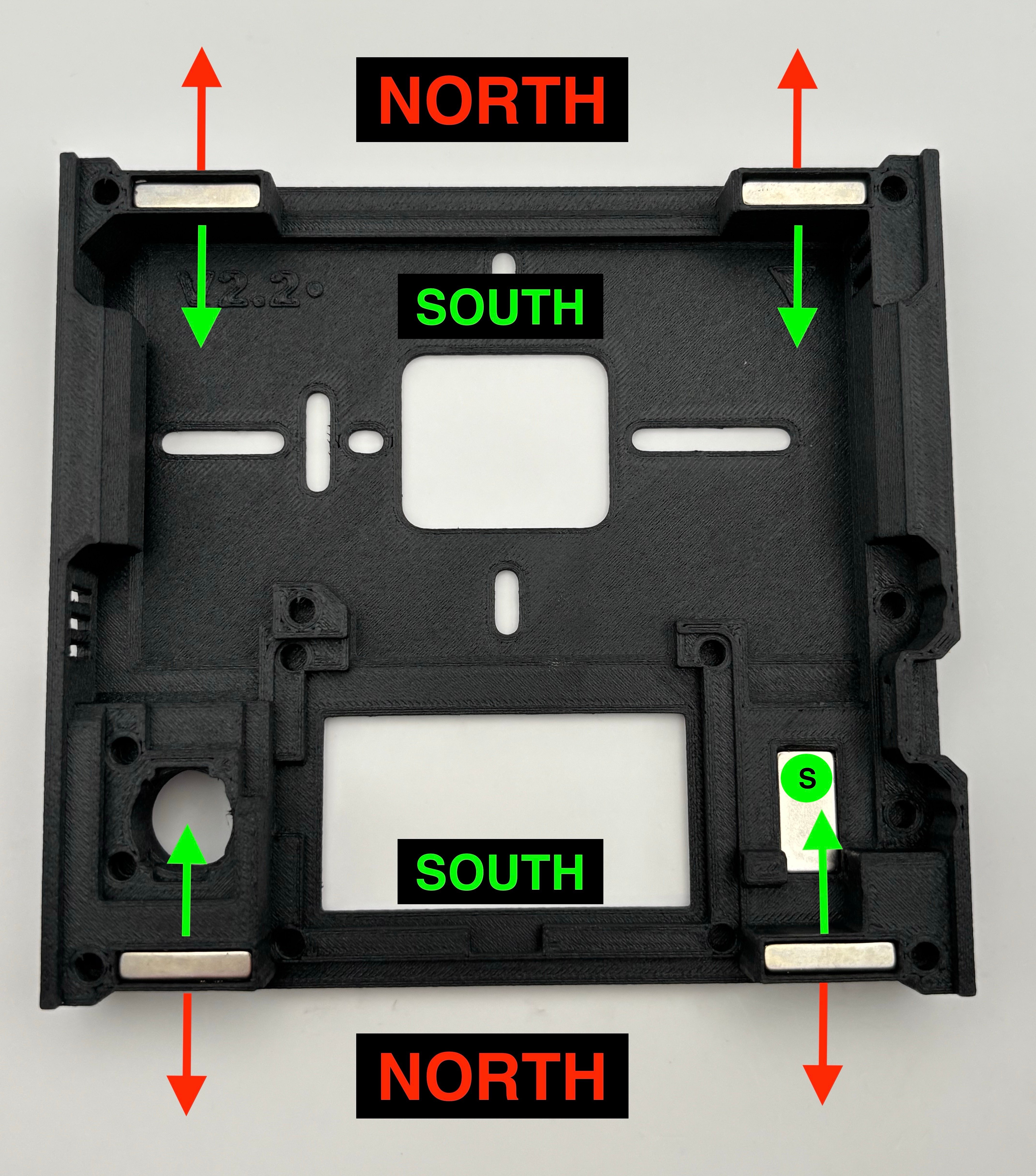
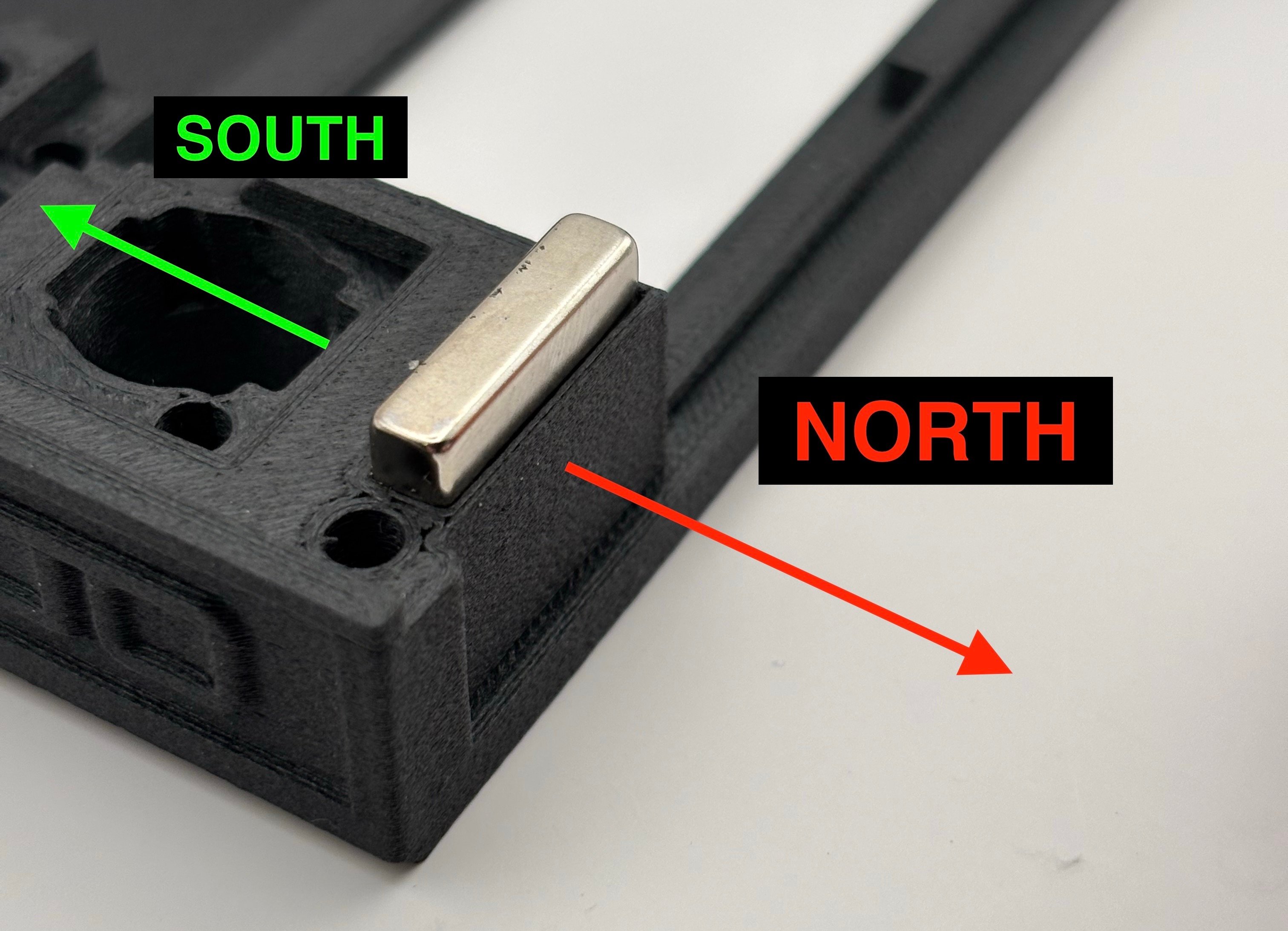
        Insert 4x thick magnets (20x10x3) into the case body for the module mounts.

        **<u>North</u>** faces should go out and away from the case.
        <Frame>
          <img src="https://mintcdn.com/shortrangetechnologies/hofaPVZFp2jsCDlP/images/IMG_6015.jpeg?fit=max&auto=format&n=hofaPVZFp2jsCDlP&q=85&s=52bbd6ca19a30b7d44bc09f63adc951b" alt="IMG 6015" title="IMG 6015" className="mx-auto" style={{ width:"67%" }} width="3024" height="2184" data-path="images/IMG_6015.jpeg" />
        </Frame>

        <Frame>
          <img src="https://mintcdn.com/shortrangetechnologies/hofaPVZFp2jsCDlP/images/IMG_6024.jpeg?fit=max&auto=format&n=hofaPVZFp2jsCDlP&q=85&s=560fc2968c79429b88ecf619a24ed84f" alt="IMG 6024" title="IMG 6024" className="mx-auto" style={{ width:"67%" }} width="4284" height="4868" data-path="images/IMG_6024.jpeg" />
        </Frame>
      </Step>

      <Step title="Install End Cap Magnets" titleSize="h3">
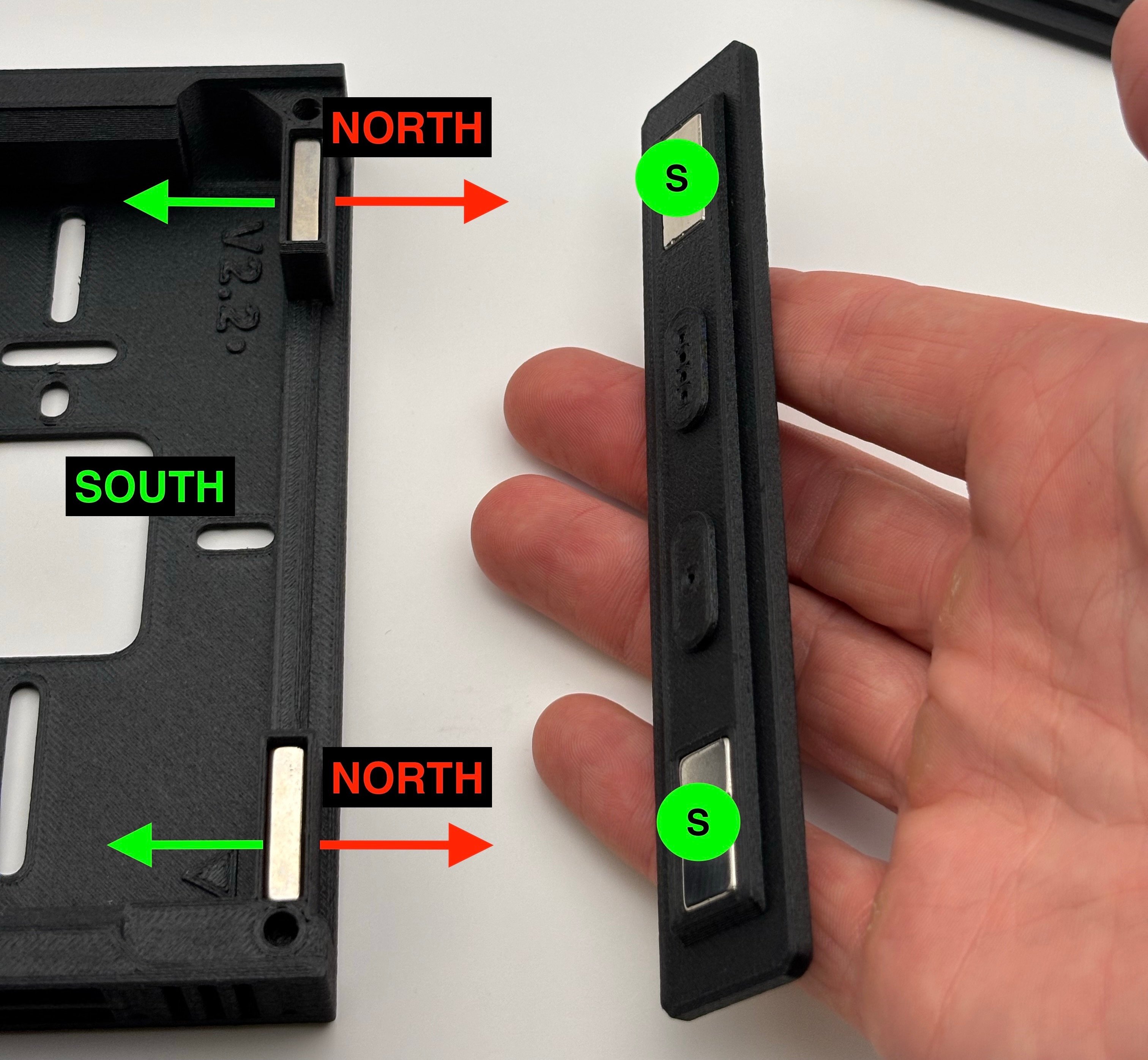
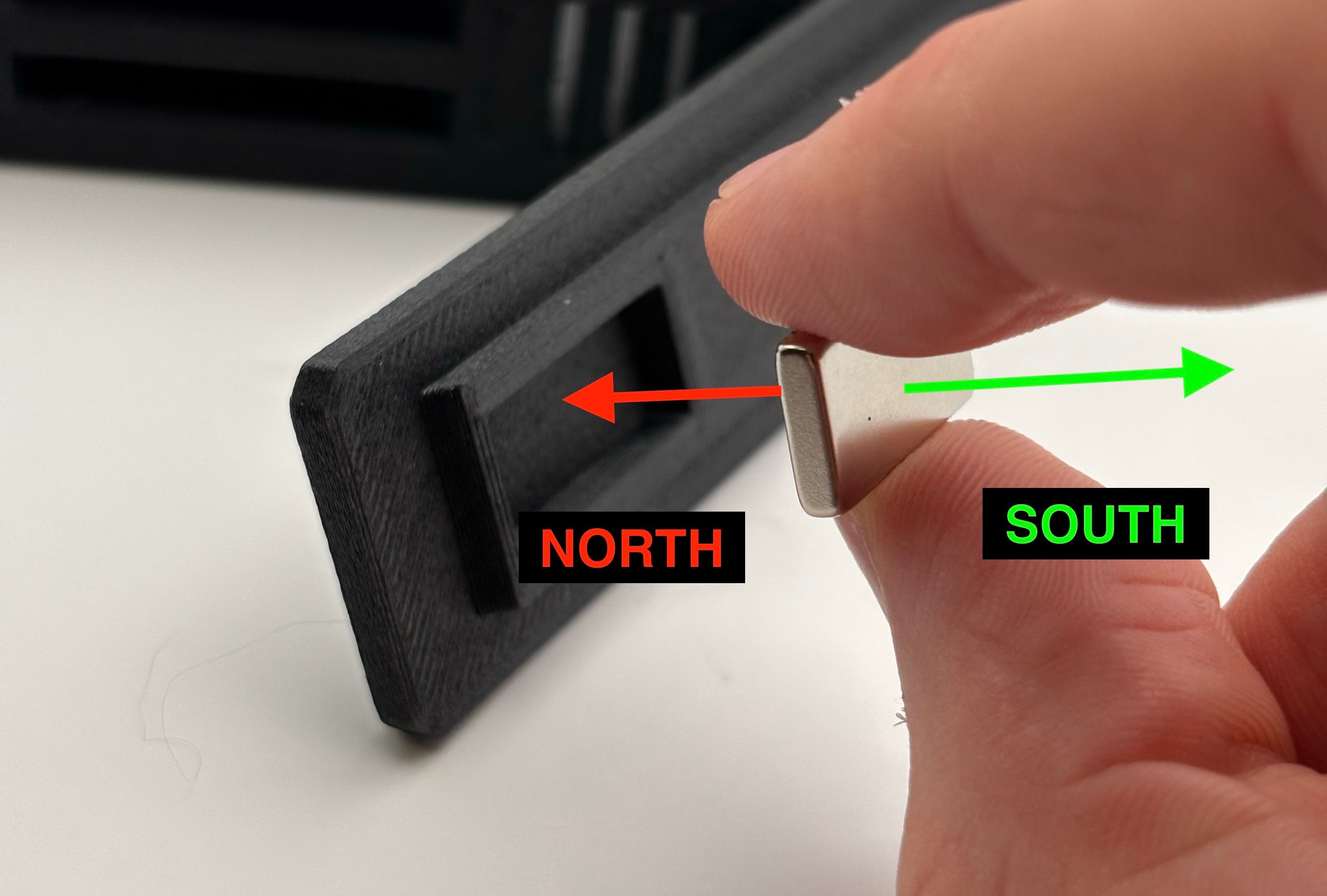
        Insert 4x thin magnets (20x10x3) into the end caps.

        Only the **<u>south</u>** side of the magnet should be visible after insertion.

        After insertion, test that the end caps snap to the case!

        <Tip>
          If magnets do not stay seated in the end caps, use some industrial superglue.
        </Tip>

        <Frame>
          <img src="https://mintcdn.com/shortrangetechnologies/tWhDIgxYtiVckSZb/images/IMG_6029.jpeg?fit=max&auto=format&n=tWhDIgxYtiVckSZb&q=85&s=922673730549d903ca5173278859a963" alt="IMG 6029" width="3024" height="2042" data-path="images/IMG_6029.jpeg" />
        </Frame>

        <Frame>
          <img src="https://mintcdn.com/shortrangetechnologies/EX74XmSyN484u514/images/IMG_6030.jpeg?fit=max&auto=format&n=EX74XmSyN484u514&q=85&s=fca1ffb4ba9a9b31d72087b149ba7662" alt="IMG 6030" width="3024" height="2791" data-path="images/IMG_6030.jpeg" />
        </Frame>
      </Step>

      <Step title="Install Mag Ring" titleSize="h3">
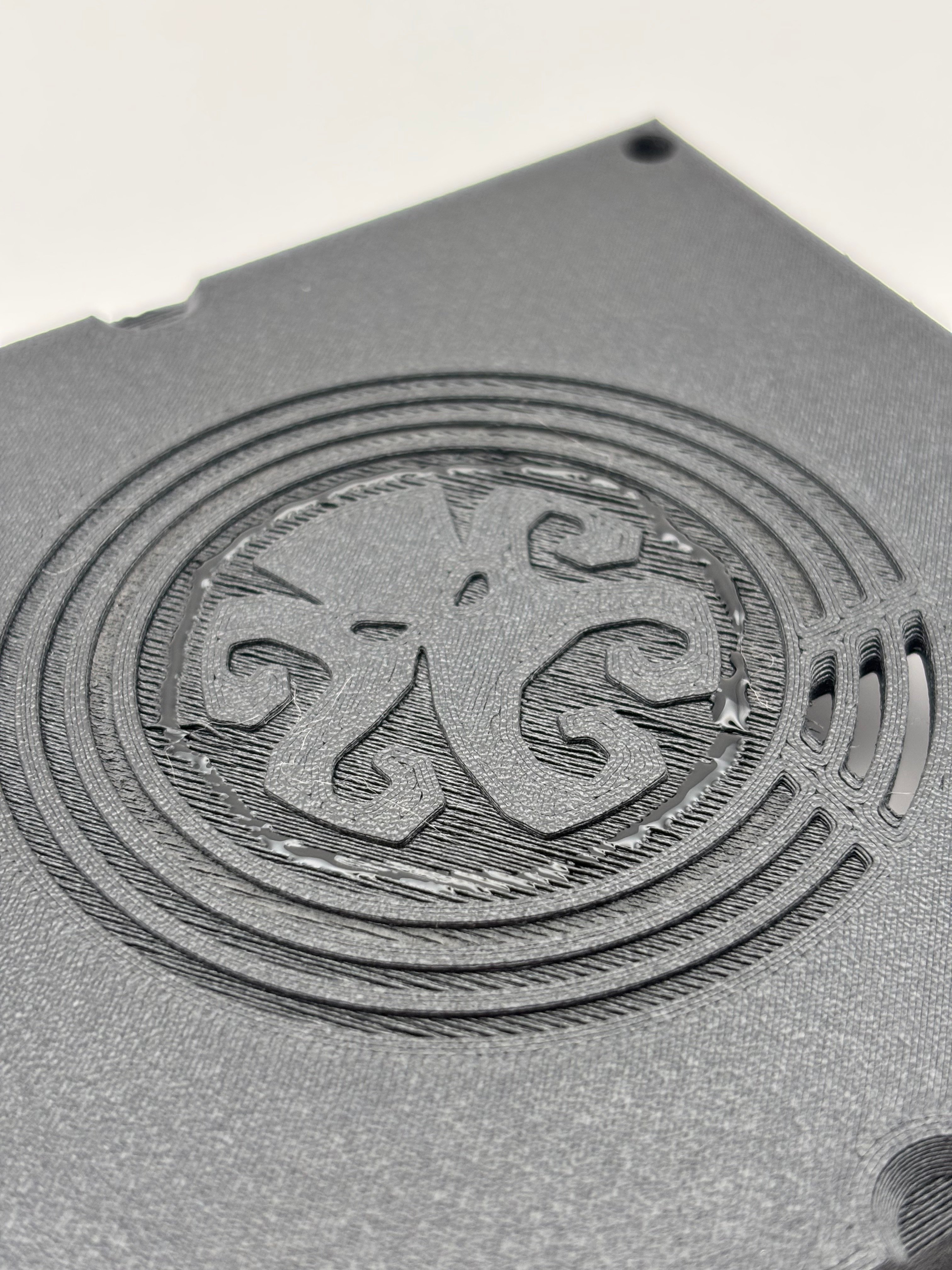
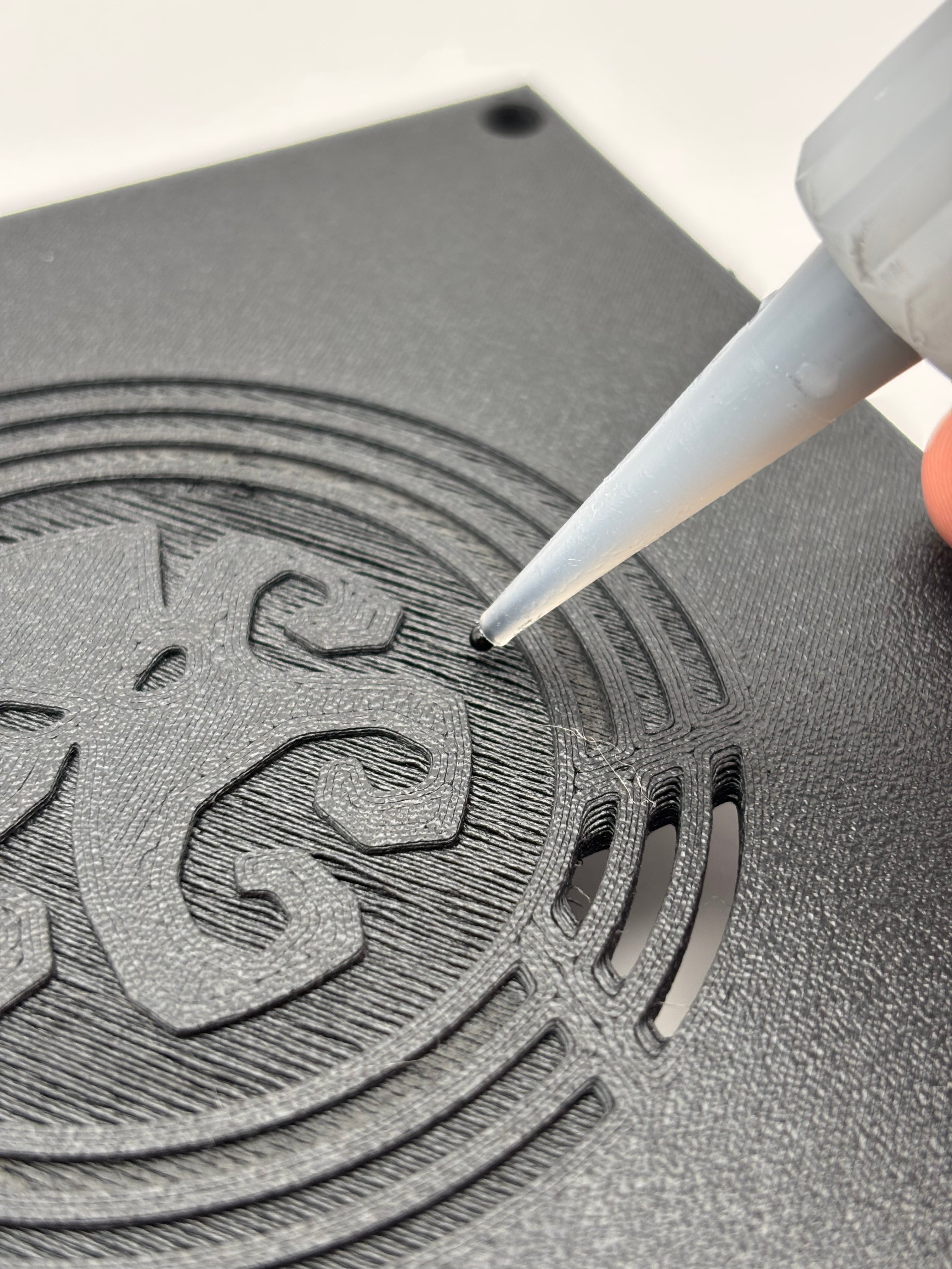
        Lay down a very thin line of industrial superglue in the  ring circle on the case lid.
        <Columns cols={2}>
          <Column>
            <Frame>
              <img src="https://mintcdn.com/shortrangetechnologies/Q9OtFI5KyE2FreO0/images/IMG_6051.jpeg?fit=max&auto=format&n=Q9OtFI5KyE2FreO0&q=85&s=60a1efd8f46233b22d862ac46f2d1e25" alt="IMG 6051" width="4032" height="3024" data-path="images/IMG_6051.jpeg" />
            </Frame>
          </Column>

          <Column>
            <Frame>
              <img src="https://mintcdn.com/shortrangetechnologies/Q9OtFI5KyE2FreO0/images/IMG_6052.jpeg?fit=max&auto=format&n=Q9OtFI5KyE2FreO0&q=85&s=b7c3e56c90b7882d6e89bf33cb5bf770" alt="IMG 6052" width="4032" height="3024" data-path="images/IMG_6052.jpeg" />
            </Frame>
          </Column>
        </Columns>

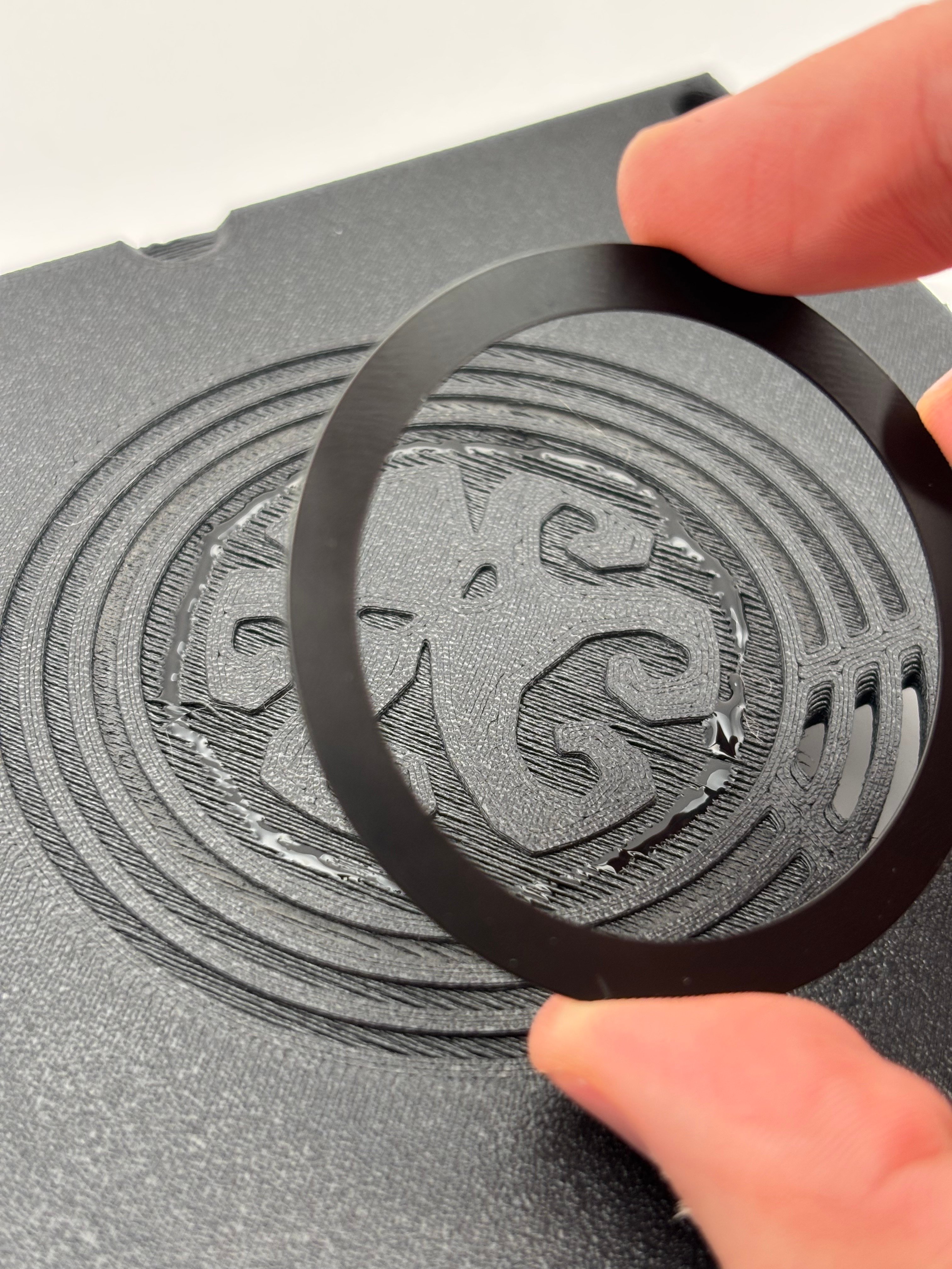
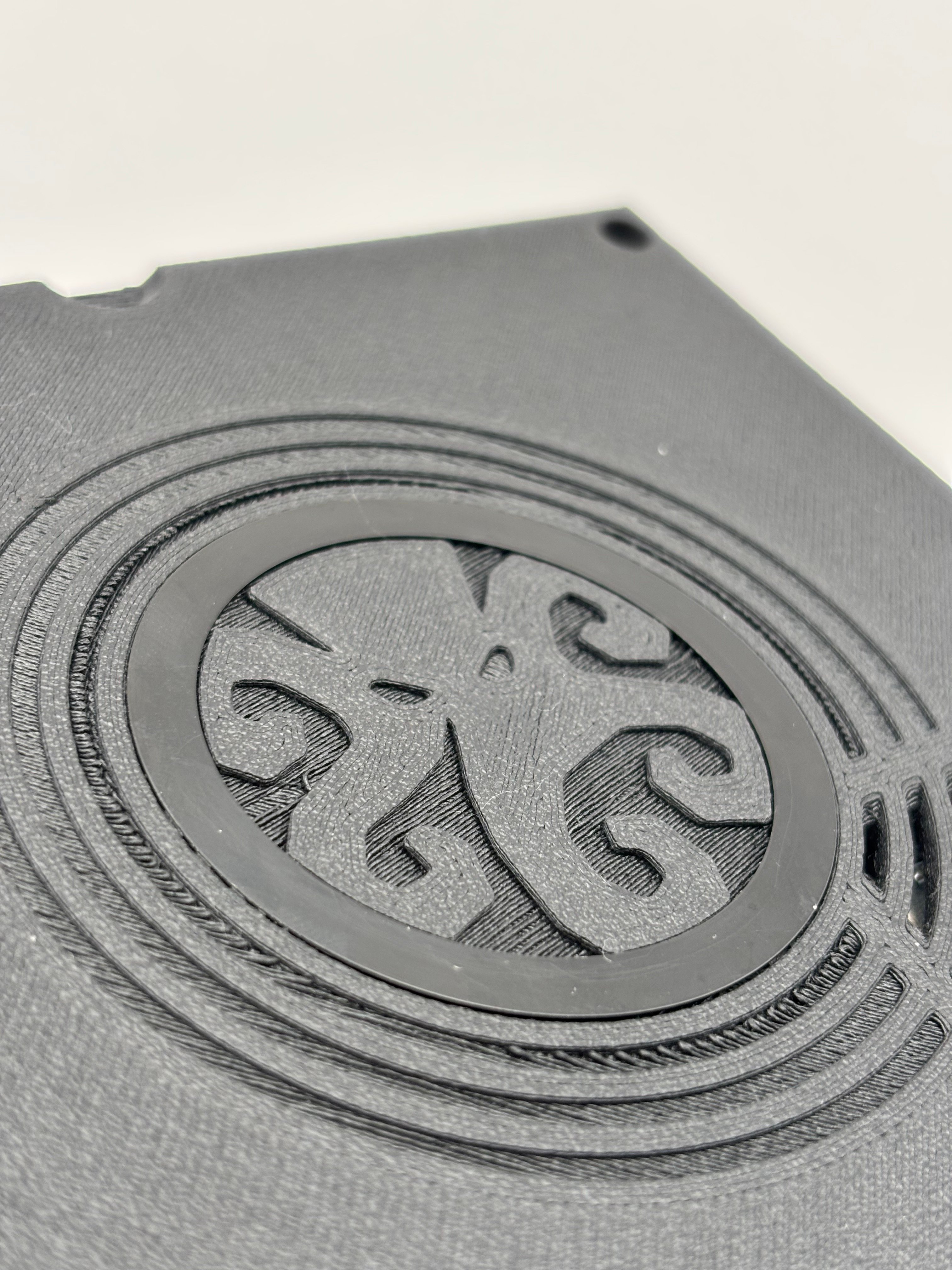
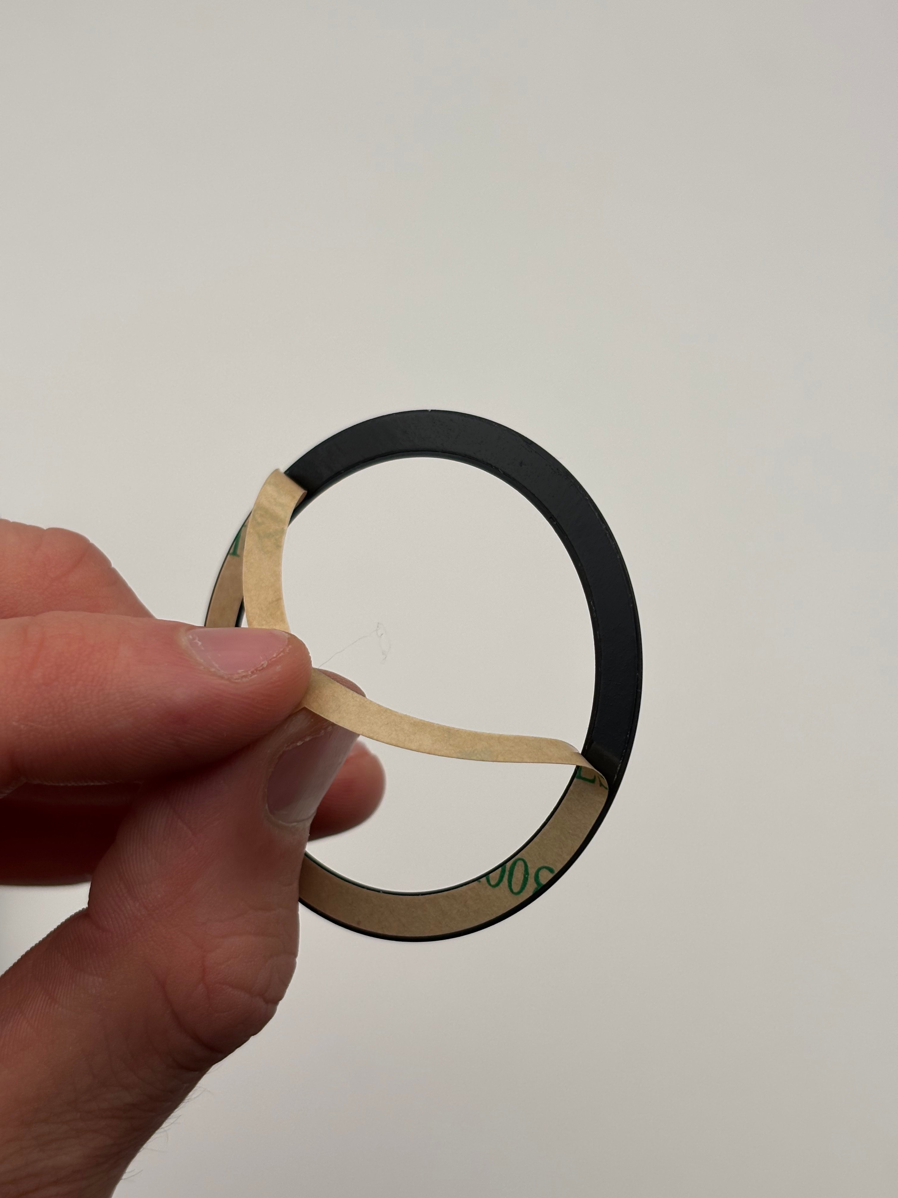
        Remove backing from magnetic ring, align, and install.
        <Columns cols={3}>
          <Column>
            <Frame>
              <img src="https://mintcdn.com/shortrangetechnologies/Q9OtFI5KyE2FreO0/images/IMG_6047.jpeg?fit=max&auto=format&n=Q9OtFI5KyE2FreO0&q=85&s=d6332f684bf0f31db1c25a9e0972c563" alt="IMG 6047" width="4032" height="3024" data-path="images/IMG_6047.jpeg" />
            </Frame>
          </Column>

          <Column>
            <Frame>
              <img src="https://mintcdn.com/shortrangetechnologies/Q9OtFI5KyE2FreO0/images/IMG_6054.jpeg?fit=max&auto=format&n=Q9OtFI5KyE2FreO0&q=85&s=d6e072740dd50cbbb17e550a4845be46" alt="IMG 6054" width="4032" height="3024" data-path="images/IMG_6054.jpeg" />
            </Frame>
          </Column>

          <Column>
            <Frame>
              <img src="https://mintcdn.com/shortrangetechnologies/Q9OtFI5KyE2FreO0/images/IMG_6056.jpeg?fit=max&auto=format&n=Q9OtFI5KyE2FreO0&q=85&s=389666a1b9b2e9f9b32d17a2d6194c4e" alt="IMG 6056" width="4032" height="3024" data-path="images/IMG_6056.jpeg" />
            </Frame>
          </Column>
        </Columns>
      </Step>
    </Steps>
  </Step>

  <Step title="STEP TWO: THREADED INSERTS" icon="fire" titleSize="h2">
    <Warning>
      Plastic gives off harmful fumes when heated or burned. Work in a well ventilated area and avoid direct inhalation.
    </Warning>

    <Steps>
      <Step title="Align Threaded Inserts" titleSize="h3">
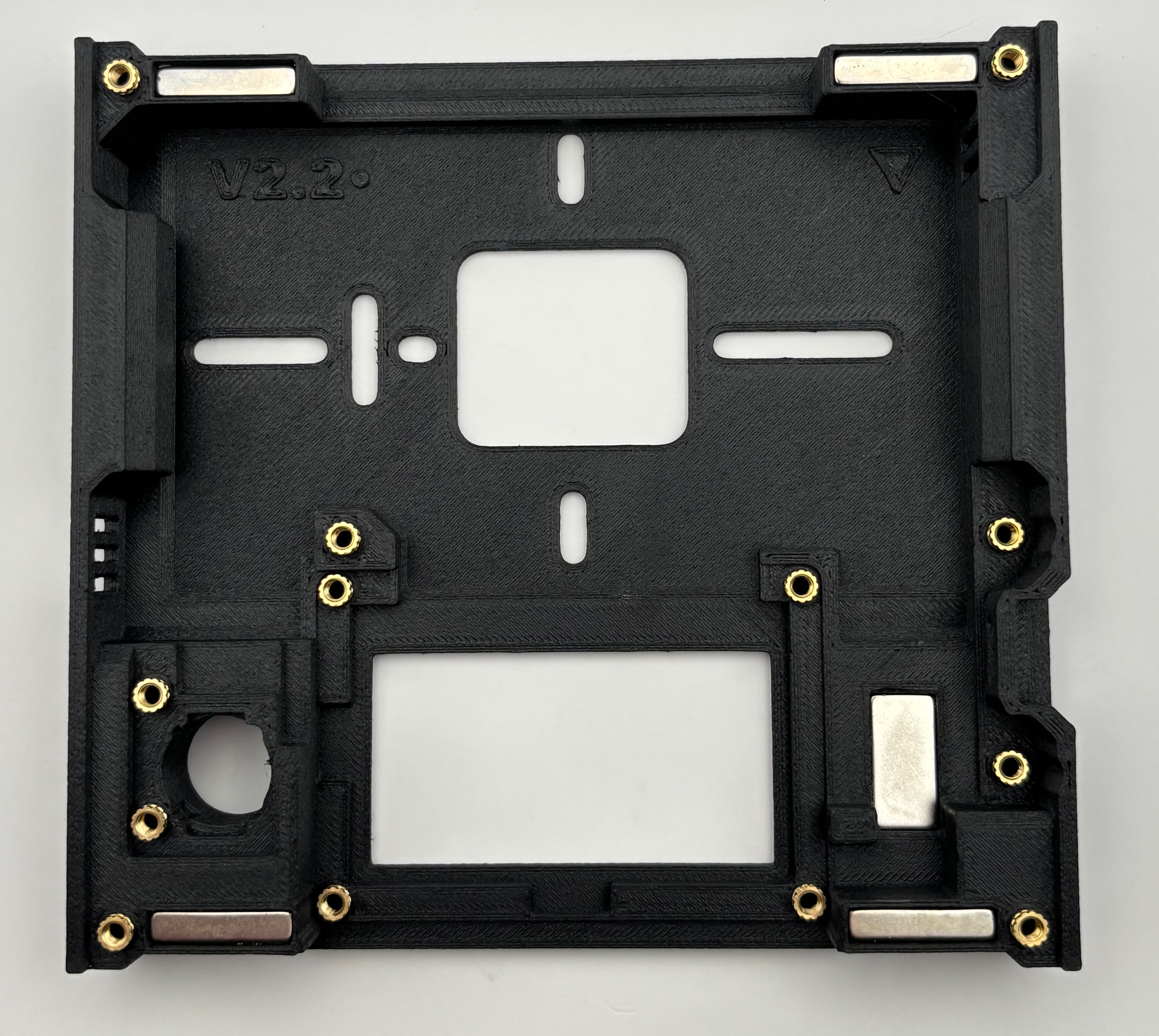
        Align 13x threaded inserts over the insert holes. The small end of the insert should set nicely in the insert hole.
        <Frame>
          <img src="https://mintcdn.com/shortrangetechnologies/s1g9zV1XdGGQL-Gx/images/IMG_6037.jpeg?fit=max&auto=format&n=s1g9zV1XdGGQL-Gx&q=85&s=583356be60059f99125268bdb389f2fb" alt="IMG 6037" width="4284" height="3832" data-path="images/IMG_6037.jpeg" />
        </Frame>
      </Step>

      <Step title="Heat Press Threaded Inserts" titleSize="h3">
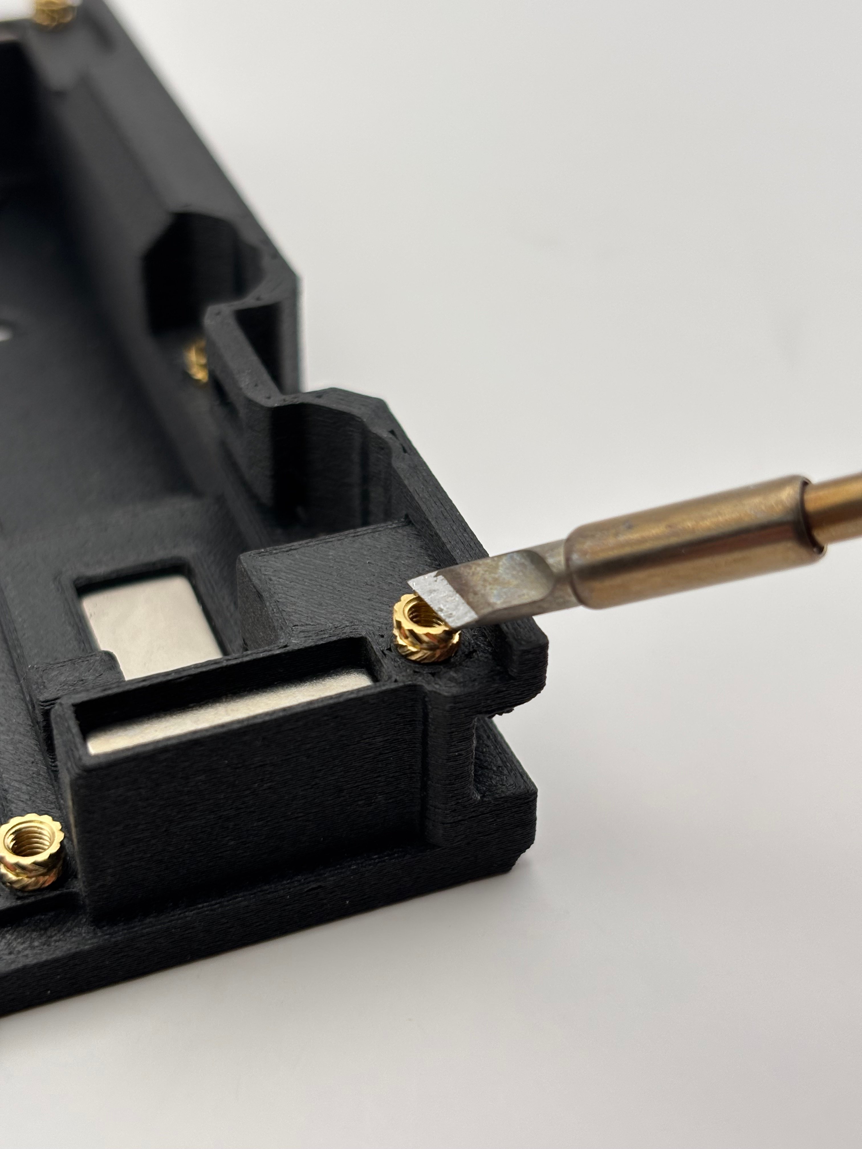
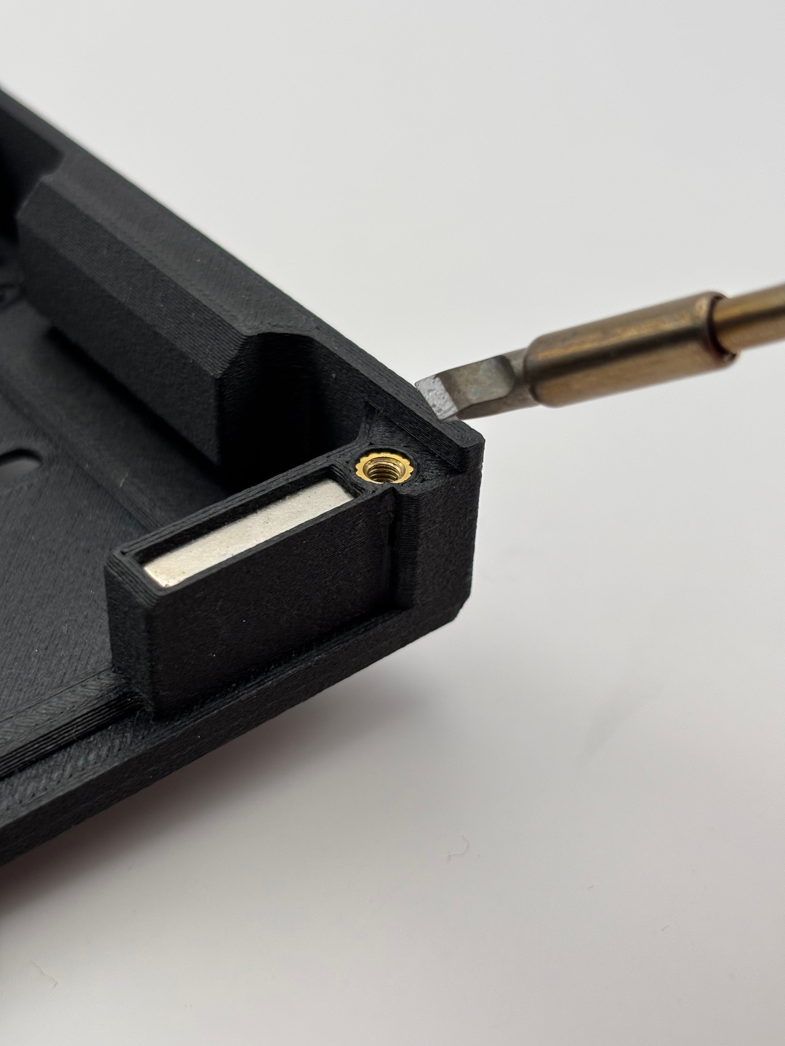
        Once inserts are aligned, heat press with a soldering iron or threaded insert press. **Inserts should end up flush or slightly under the body line**.
        <Columns cols={2}>
          <Column>
            <Frame>
              <img src="https://mintcdn.com/shortrangetechnologies/s1g9zV1XdGGQL-Gx/images/IMG_6040.jpeg?fit=max&auto=format&n=s1g9zV1XdGGQL-Gx&q=85&s=ecee1a78cfeff6a4bd7e7e0af3872172" alt="IMG 6040" width="4032" height="3024" data-path="images/IMG_6040.jpeg" />
            </Frame>
          </Column>

          <Column>
            <Frame>
              <img src="https://mintcdn.com/shortrangetechnologies/s1g9zV1XdGGQL-Gx/images/IMG_6042.jpeg?fit=max&auto=format&n=s1g9zV1XdGGQL-Gx&q=85&s=75e4ca614ec7982ab7b0f3224013acd5" alt="IMG 6042" width="4032" height="3024" data-path="images/IMG_6042.jpeg" />
            </Frame>
          </Column>
        </Columns>
      </Step>
    </Steps>
  </Step>

  <Step title="STEP THREE: COMPONENTS" icon="bolt-lightning" titleSize="h2">
    <Steps>
      <Step title="Install OLED Screen" titleSize="h3">
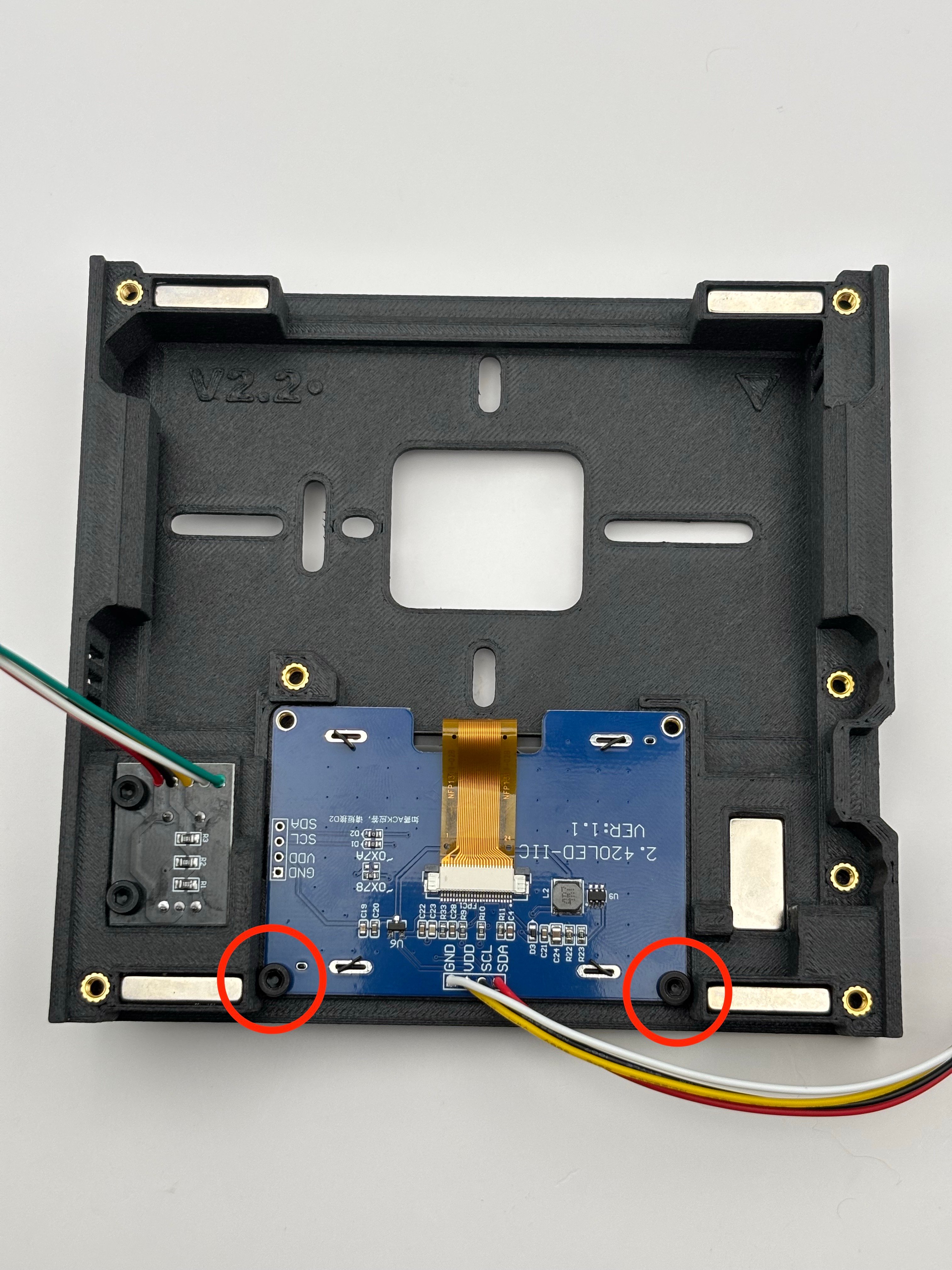
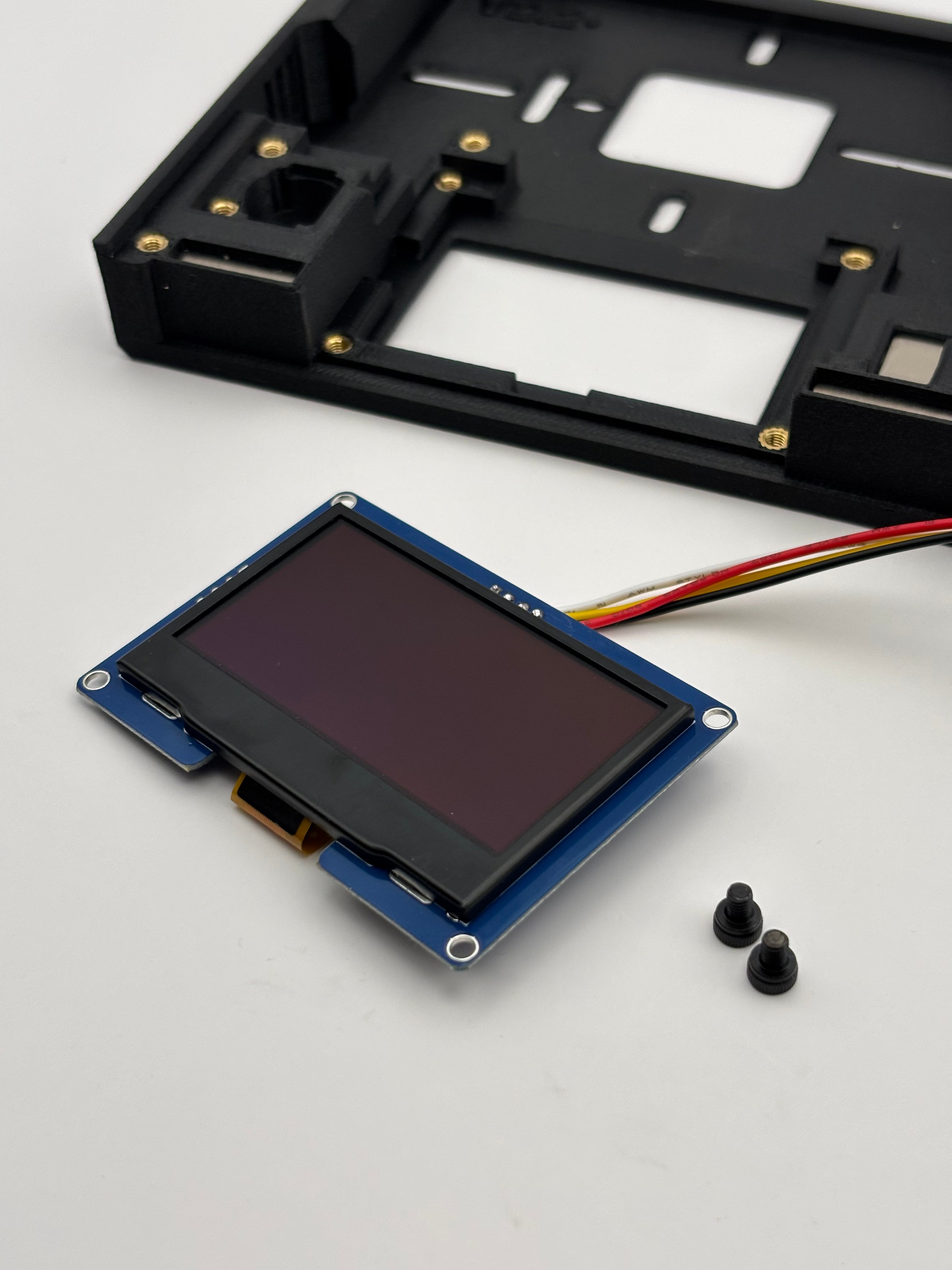
        Mount the OLED screen using 2x short screws (M3x4) on the **<u>outermost mounting holes, leaving the innermost mounting holes clear</u>** to allow for other components.

        <Warning>
          Mounting the OLED using the two innermost holes will make it so your other components do not sit flush. If you wish to use those threads, obtaining a flatter or lower profile screw would allow for sufficient clearance. We have found mounting the screen with the outermost holes to be sufficient.
        </Warning>

        <Columns cols={2}>
          <Column>
            <Frame>
              <img src="https://mintcdn.com/shortrangetechnologies/fdQ3MQ8btiug1R1I/images/IMG_6058.jpeg?fit=max&auto=format&n=fdQ3MQ8btiug1R1I&q=85&s=052976914c428918ddd8d46d10f34bc2" alt="IMG 6058" width="4032" height="3024" data-path="images/IMG_6058.jpeg" />
            </Frame>
          </Column>

          <Column>
            <Frame>
              <img src="https://mintcdn.com/shortrangetechnologies/fdQ3MQ8btiug1R1I/images/IMG_6066.jpeg?fit=max&auto=format&n=fdQ3MQ8btiug1R1I&q=85&s=d42fe969a86cc99d97096f5564cd99c0" alt="IMG 6066" width="3024" height="4032" data-path="images/IMG_6066.jpeg" />
            </Frame>
          </Column>
        </Columns>
      </Step>

      <Step title="Install Encoder and Knob" titleSize="h3">
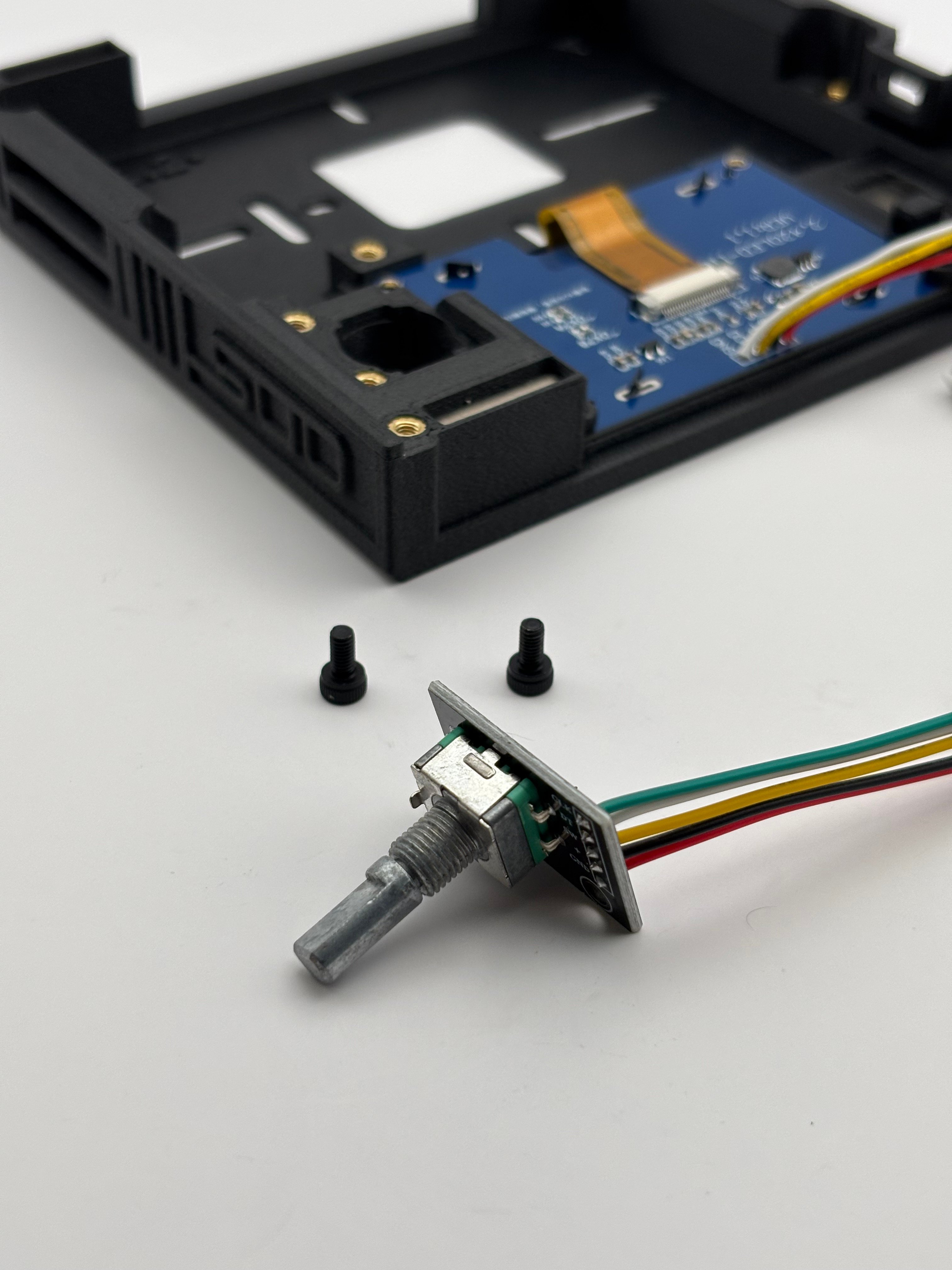
        Mount the encoder using 2x long screws (M3x6).
        <Columns cols={2}>
          <Column>
            <Frame>
              <img src="https://mintcdn.com/shortrangetechnologies/fdQ3MQ8btiug1R1I/images/IMG_6063.jpeg?fit=max&auto=format&n=fdQ3MQ8btiug1R1I&q=85&s=25d4636980dc3c06e914120fabf674be" alt="IMG 6063" width="4032" height="3024" data-path="images/IMG_6063.jpeg" />
            </Frame>
          </Column>

          <Column>
            <Frame>
              <img src="https://mintcdn.com/shortrangetechnologies/fdQ3MQ8btiug1R1I/images/IMG_6065.jpeg?fit=max&auto=format&n=fdQ3MQ8btiug1R1I&q=85&s=d9015125f682e794cd1d033cc8045d6a" alt="IMG 6065" width="4032" height="3024" data-path="images/IMG_6065.jpeg" />
            </Frame>
          </Column>
        </Columns>

        Once mounted, slide the knob on the encoder post from the other side.
      </Step>

      <Step title="Install OpenDoorSim Board" titleSize="h3">
        <Tip>
          You may want to jump forward one step and connect your reader to the ODS board before fully mounting.
        </Tip>

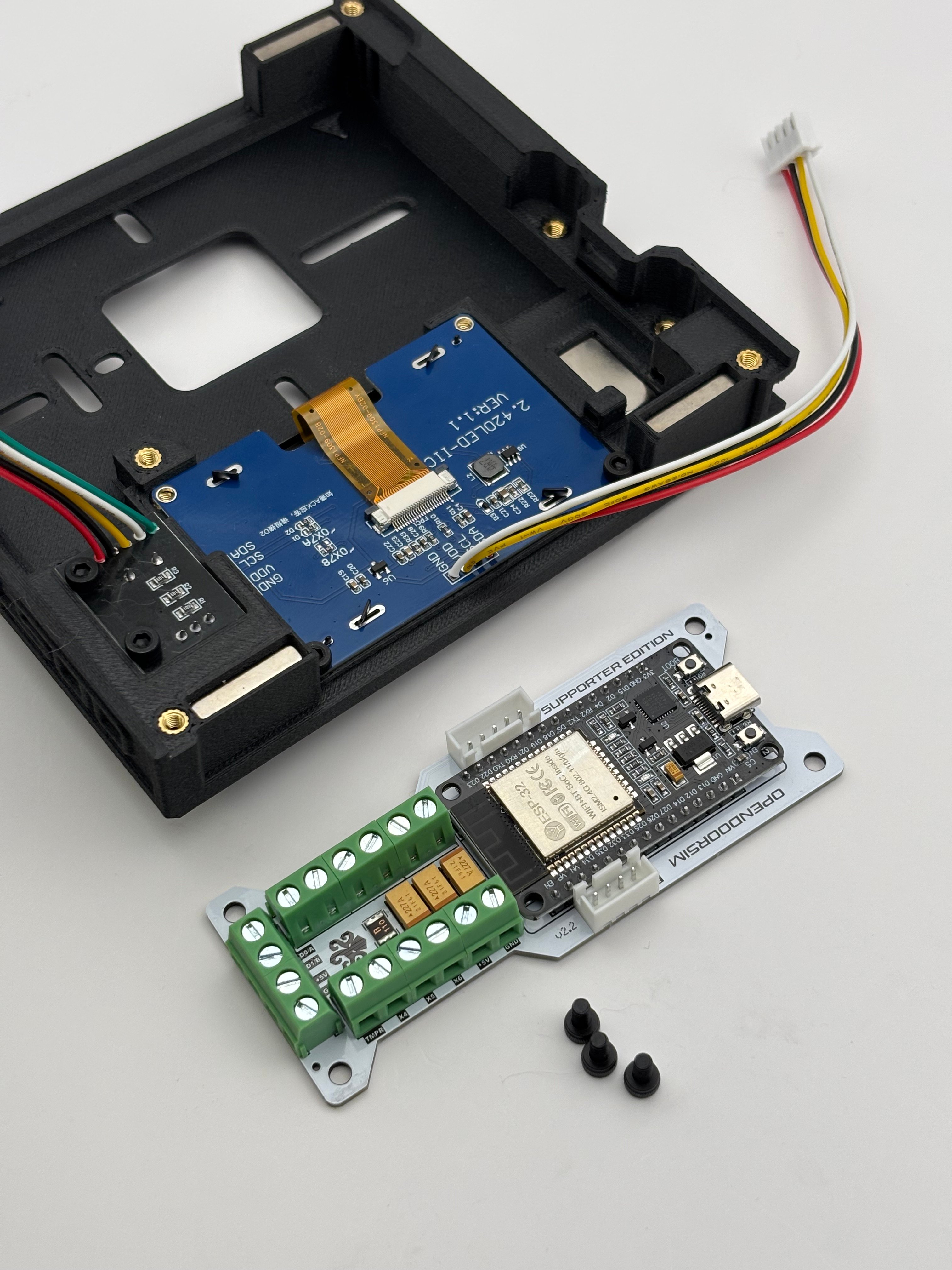
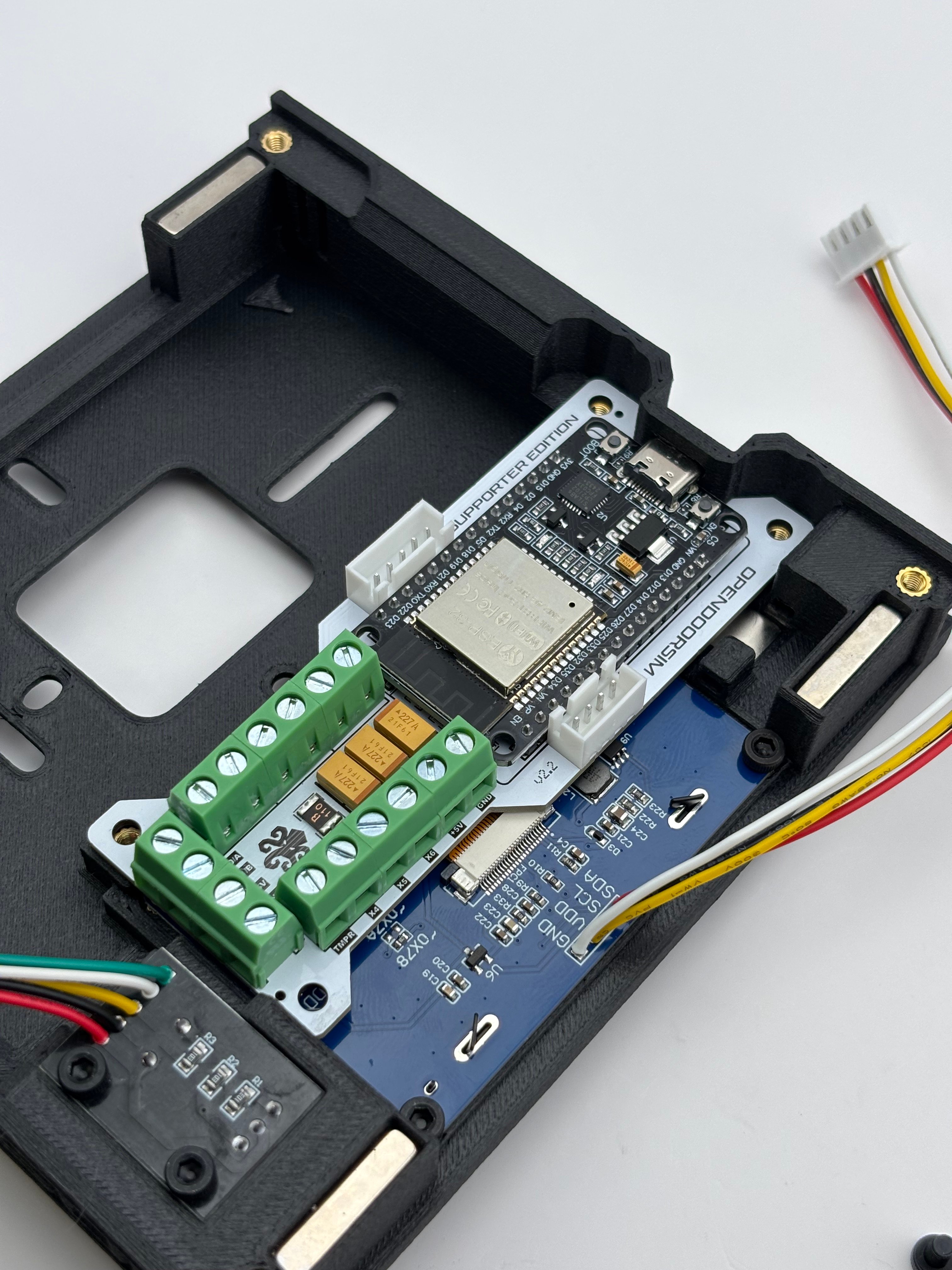
        Carefully slide the OpenDoorSim Board into position, pressing down and aligning the USB-C port with the case hole before pressing down and sliding the board into place.
        <Columns cols={2}>
          <Column>
            <Frame>
              <img src="https://mintcdn.com/shortrangetechnologies/fdQ3MQ8btiug1R1I/images/IMG_6068.jpeg?fit=max&auto=format&n=fdQ3MQ8btiug1R1I&q=85&s=7a098affc2a1464a841492627d861e77" alt="IMG 6068" width="4032" height="3024" data-path="images/IMG_6068.jpeg" />
            </Frame>
          </Column>

          <Column>
            <Frame>
              <img src="https://mintcdn.com/shortrangetechnologies/fdQ3MQ8btiug1R1I/images/IMG_6069.jpeg?fit=max&auto=format&n=fdQ3MQ8btiug1R1I&q=85&s=a56867c1f6bff7750df66cf3d03f291f" alt="IMG 6069" width="4032" height="3024" data-path="images/IMG_6069.jpeg" />
            </Frame>
          </Column>
        </Columns>

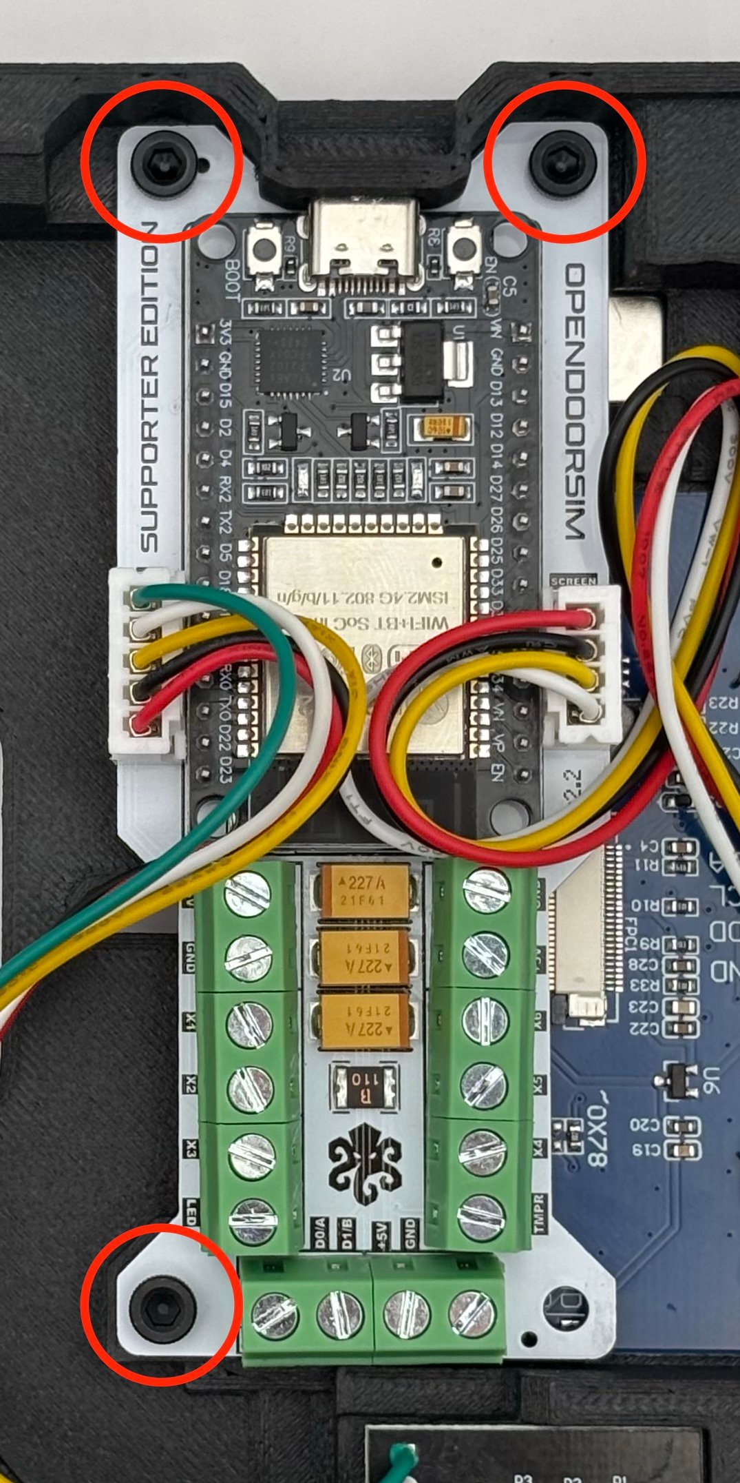
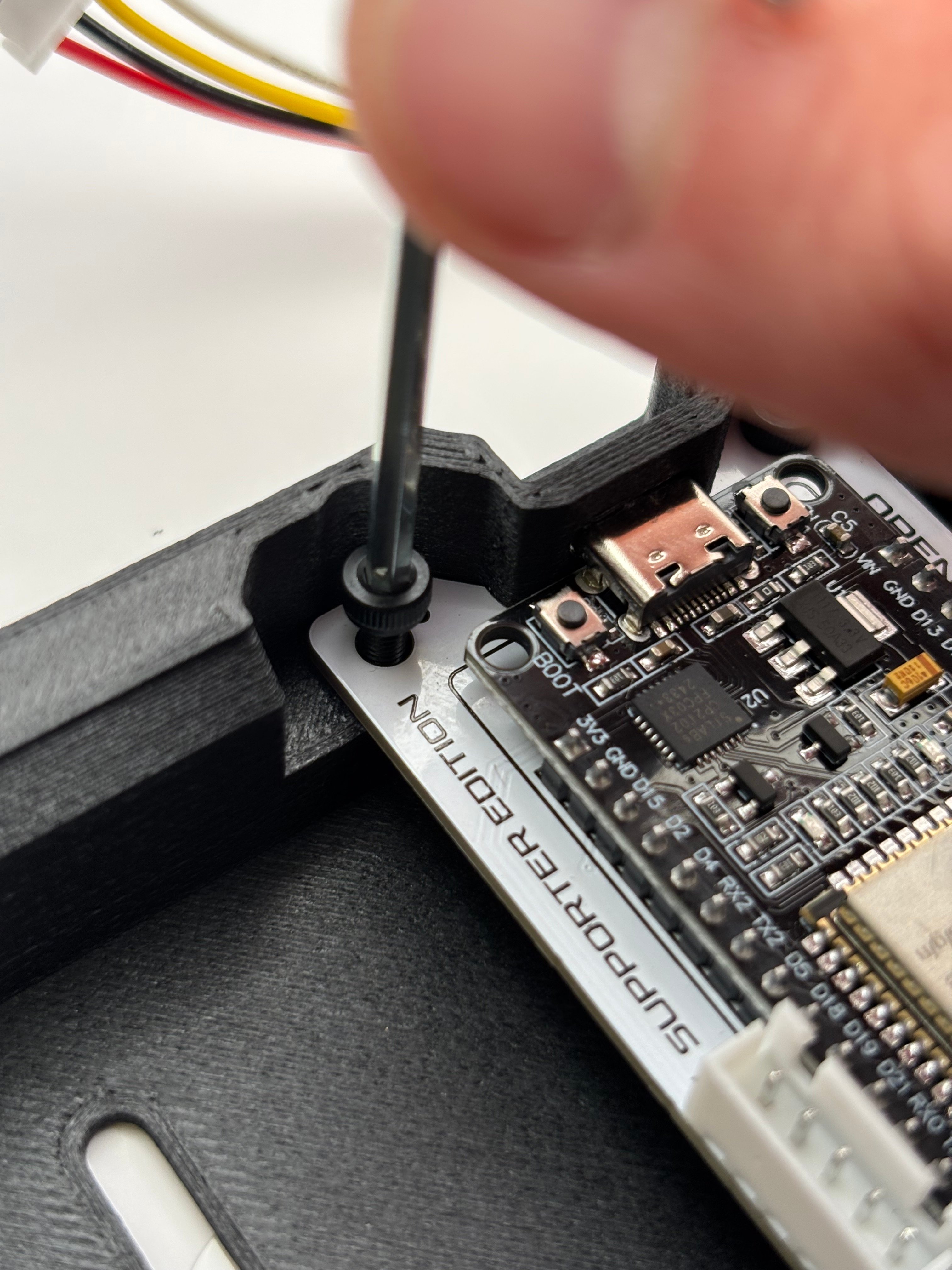
        Mount ODS Board using 3x long screws (M3x6)
        <Columns cols={2}>
          <Column>
            <Frame>
              <img src="https://mintcdn.com/shortrangetechnologies/fdQ3MQ8btiug1R1I/images/IMG_6070.jpeg?fit=max&auto=format&n=fdQ3MQ8btiug1R1I&q=85&s=71c244c1a2db08a05c9c011b72c568db" alt="IMG 6070" width="4032" height="3024" data-path="images/IMG_6070.jpeg" />
            </Frame>
          </Column>

          <Column>
            <Frame>
              <img src="https://mintcdn.com/shortrangetechnologies/fdQ3MQ8btiug1R1I/images/IMG_6074.jpeg?fit=max&auto=format&n=fdQ3MQ8btiug1R1I&q=85&s=b26596f7a96c67a577c95affdb2498db" alt="IMG 6074" title="IMG 6074" className="mx-auto" style={{ width:"67%" }} width="1075" height="2152" data-path="images/IMG_6074.jpeg" />
            </Frame>
          </Column>
        </Columns>
      </Step>

      <Step title="Connect Your Reader" titleSize="h3">
        Now is a great time to mount your reader of choice to the universal mounting plate, and connect your reader wires to the OpenDoorSim board.

        For more details, see [Connecting a Reader](/untitled-page).
      </Step>

      <Step title="Connect OLED Screen and Encoder" titleSize="h3">
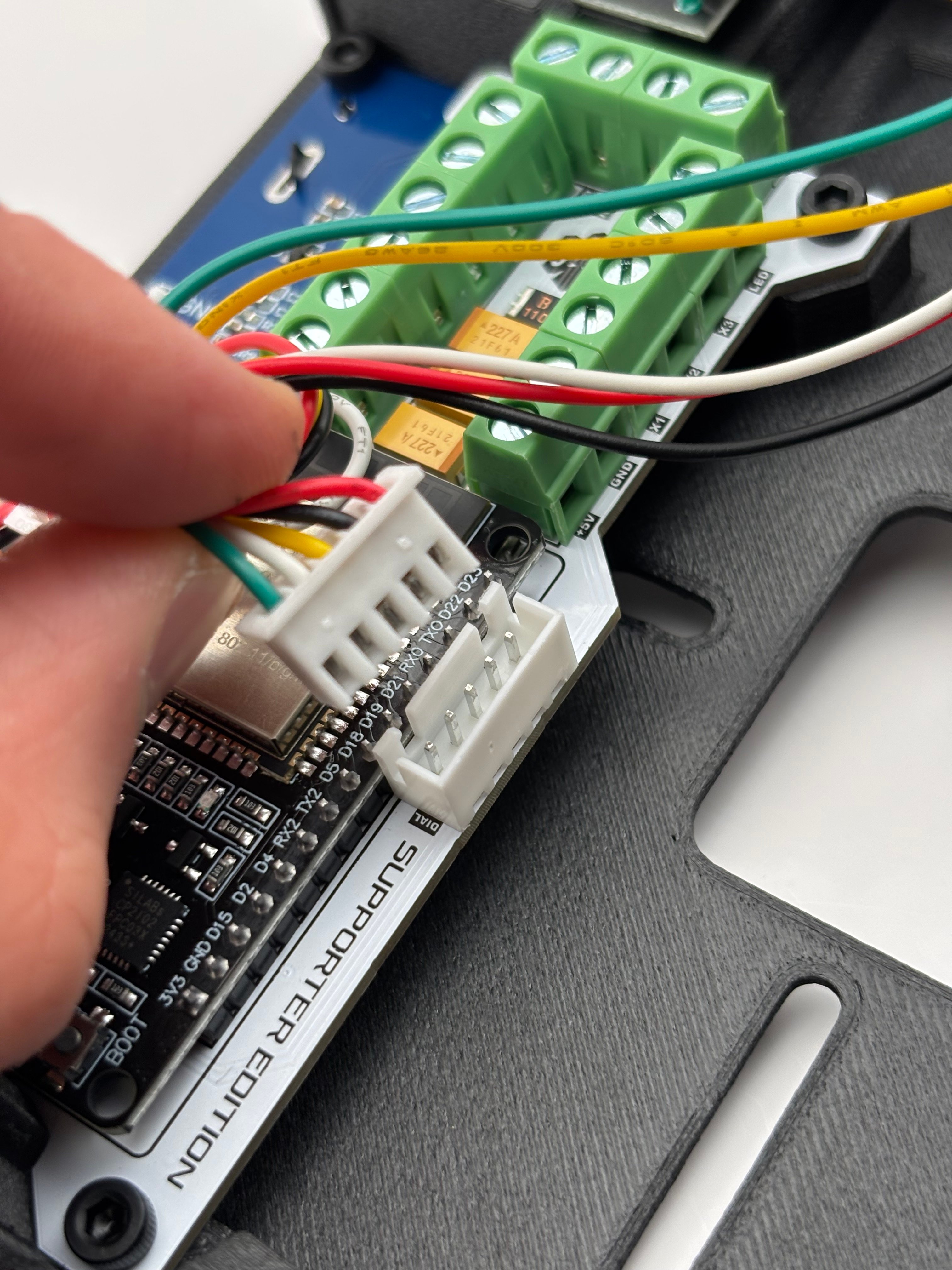
        Plug respective JST connectors from each component into their JST socket on the ODS Board.
        <Columns cols={2}>
          <Column>
            <Frame>
              <img src="https://mintcdn.com/shortrangetechnologies/fdQ3MQ8btiug1R1I/images/IMG_6075.jpeg?fit=max&auto=format&n=fdQ3MQ8btiug1R1I&q=85&s=41efce523dc64080336e6e06497e5ef5" alt="IMG 6075" width="4032" height="3024" data-path="images/IMG_6075.jpeg" />
            </Frame>
          </Column>

          <Column>
            <Frame>
              <img src="https://mintcdn.com/shortrangetechnologies/fdQ3MQ8btiug1R1I/images/IMG_6076.jpeg?fit=max&auto=format&n=fdQ3MQ8btiug1R1I&q=85&s=25b121d5efe9fbaf5e27937681a9ba9e" alt="IMG 6076" width="4032" height="3024" data-path="images/IMG_6076.jpeg" />
            </Frame>
          </Column>
        </Columns>
      </Step>

      <Step title="Install Module Wires" titleSize="h3">
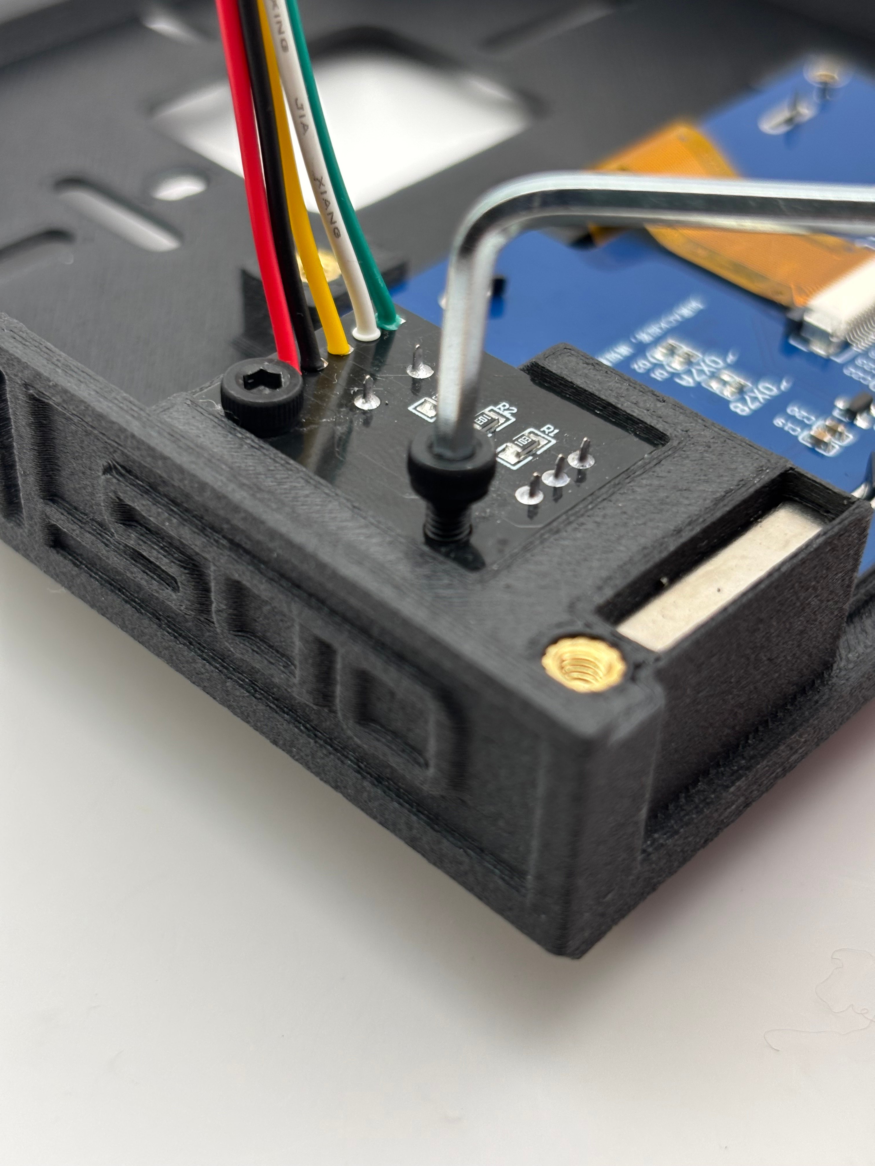
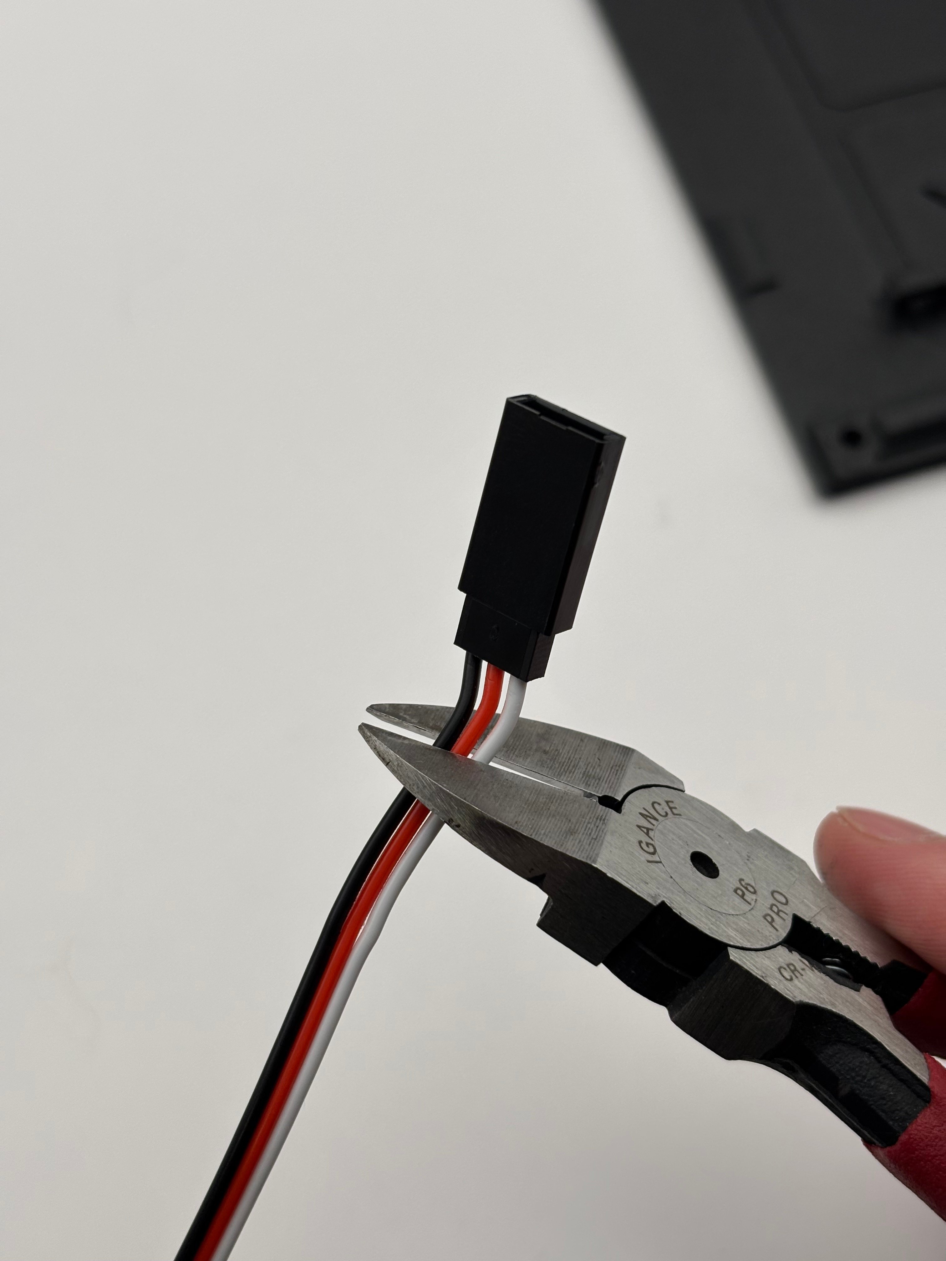
        Trim the ends of the 4x module pogo wires.

        Align the pogo wire with the mounting hole.
        <Columns cols={2}>
          <Column>
            <Frame>
              <img src="https://mintcdn.com/shortrangetechnologies/supj7QRstfZMdC5P/images/IMG_6078.jpeg?fit=max&auto=format&n=supj7QRstfZMdC5P&q=85&s=74e6d18367fcdefbfa38ffc72c7405bf" alt="IMG 6078" width="4032" height="3024" data-path="images/IMG_6078.jpeg" />
            </Frame>
          </Column>

          <Column>
            <Frame>
              <img src="https://mintcdn.com/shortrangetechnologies/supj7QRstfZMdC5P/images/IMG_6084.jpeg?fit=max&auto=format&n=supj7QRstfZMdC5P&q=85&s=24aaa06508dcfc65e7faff684a84c4f8" alt="IMG 6084" width="4032" height="3024" data-path="images/IMG_6084.jpeg" />
            </Frame>
          </Column>
        </Columns>

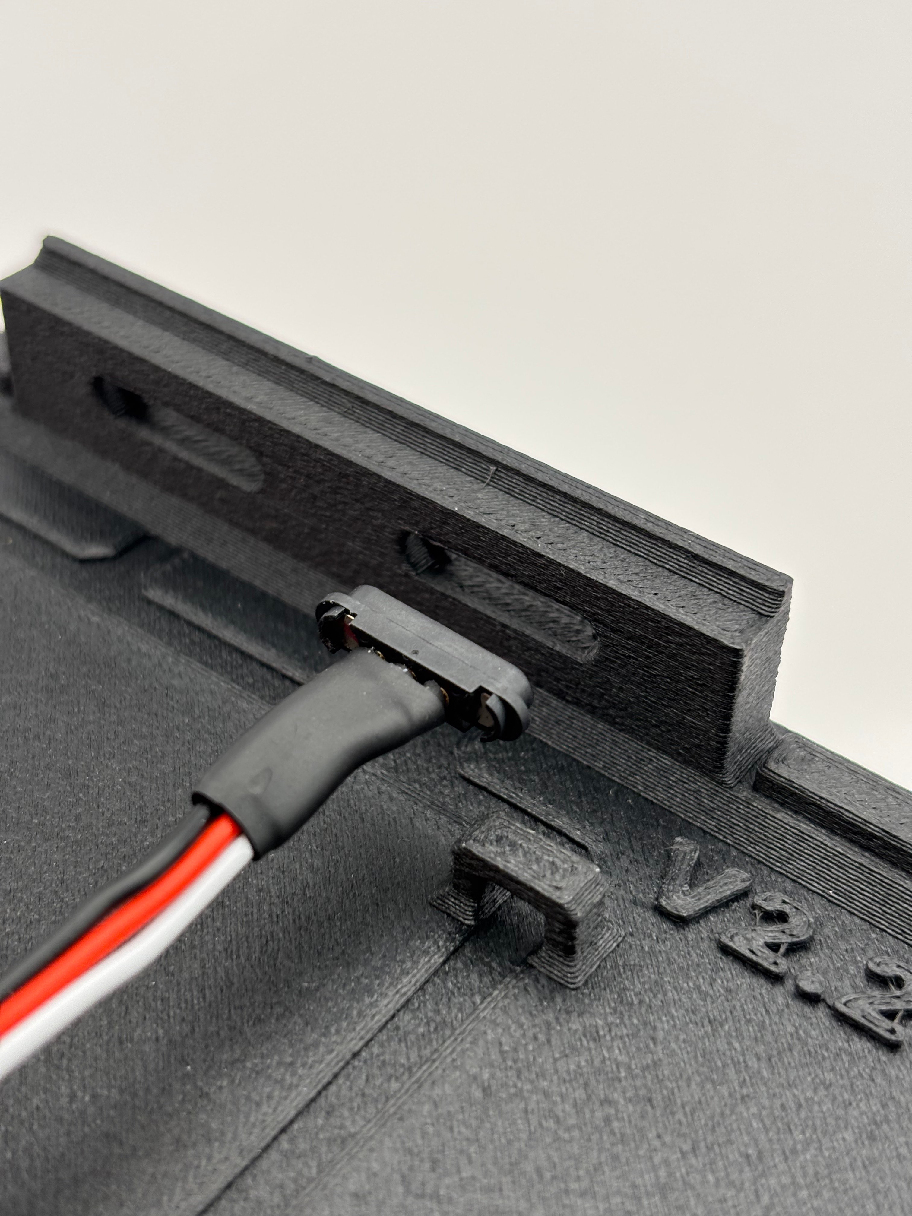
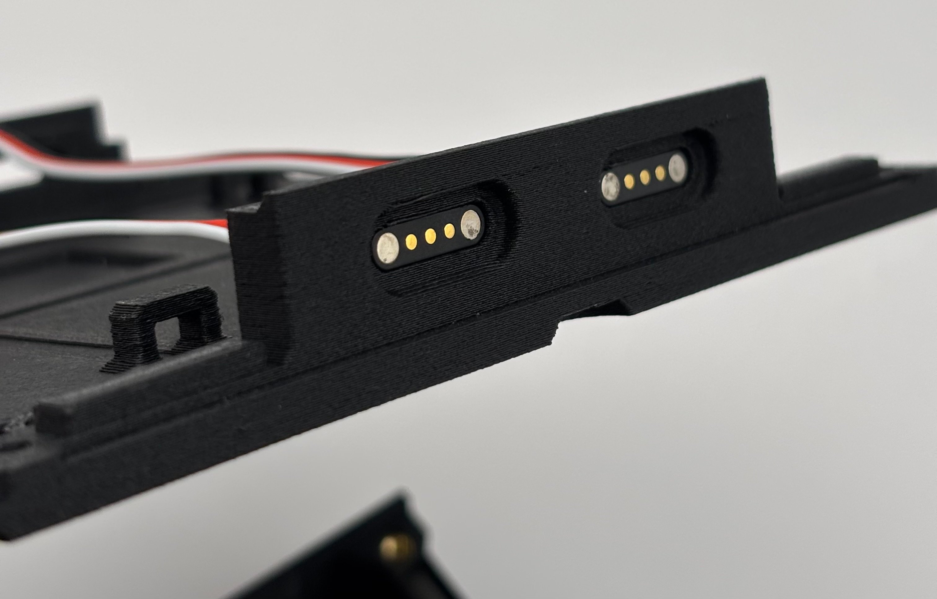
        Gently press the 4x module pogo wires into their mounting holes in the case lid.

        <Warning>
          Be careful not to press directly on the magnets of the pogo wires or you may push them out.
        </Warning>

        <Frame>
          <img src="https://mintcdn.com/shortrangetechnologies/supj7QRstfZMdC5P/images/IMG_6086-1.jpeg?fit=max&auto=format&n=supj7QRstfZMdC5P&q=85&s=bba8c47c12d02e27a6a9b2eaa899b398" alt="IMG 6086 1" width="3024" height="1934" data-path="images/IMG_6086-1.jpeg" />
        </Frame>
      </Step>
    </Steps>
  </Step>

  <Step title="STEP FOUR: CLOSING UP AND FINAL TOUCHES" icon="wand-magic-sparkles" titleSize="h2">
    <Steps>
      <Step title="Position Pogo Wires" titleSize="h3">
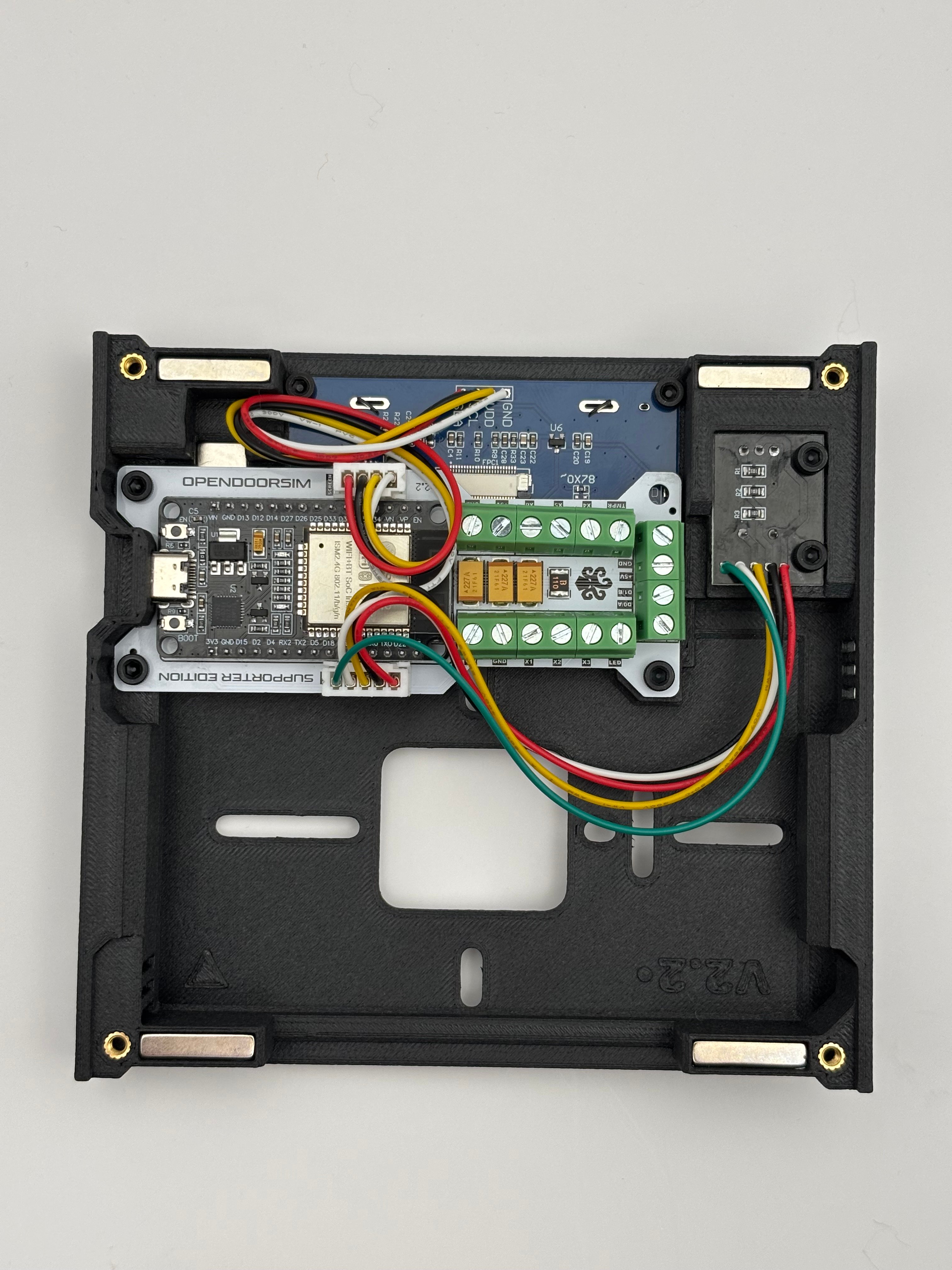
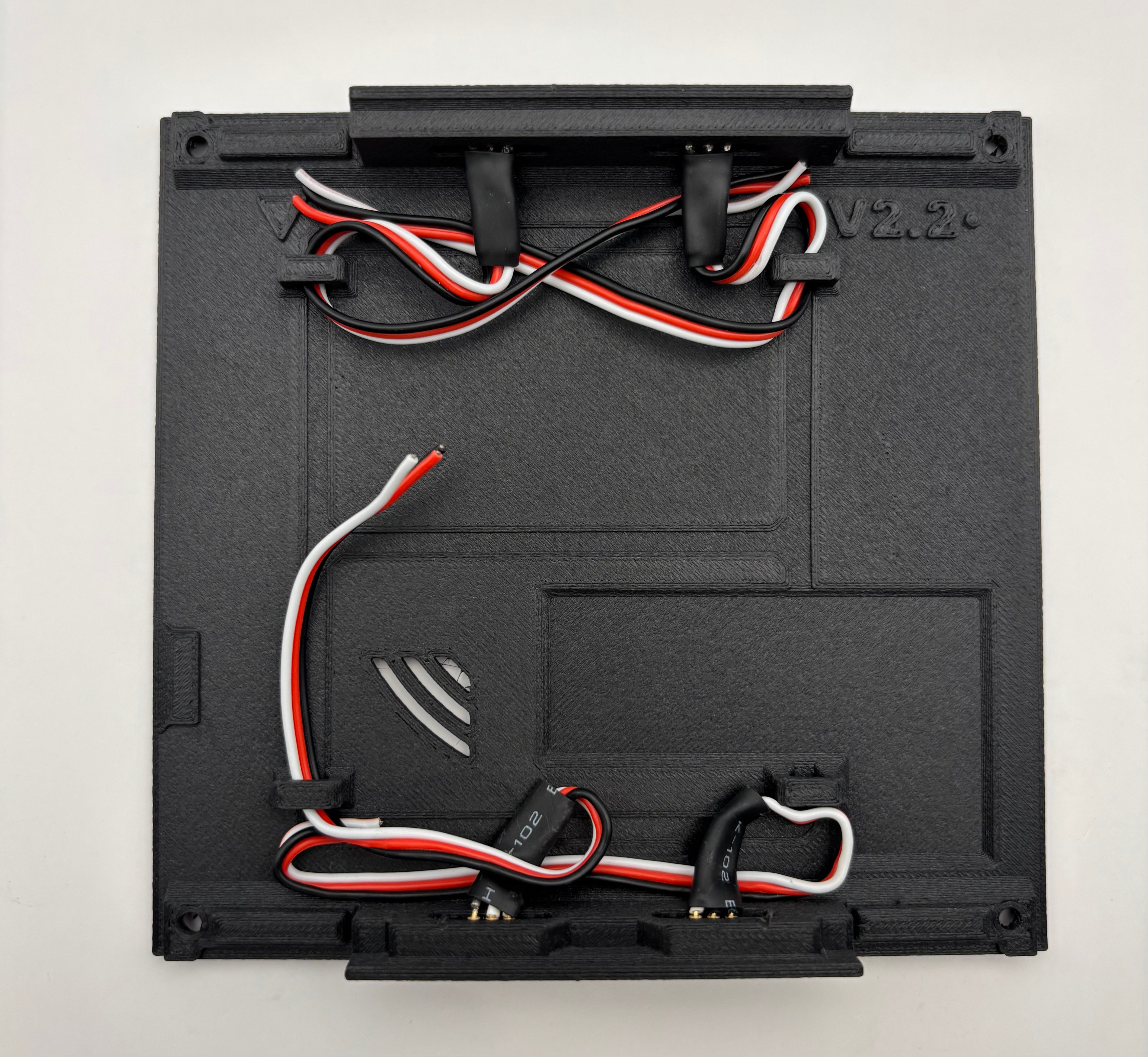
        Position the pogo wires as in the image below.

        <Warning>
          Failing to position the wires as seen below may result in the case not closing!
        </Warning>

        <Frame>
          <img src="https://mintcdn.com/shortrangetechnologies/8MyH0fcWgkOX9Ld5/images/IMG_6131.jpeg?fit=max&auto=format&n=8MyH0fcWgkOX9Ld5&q=85&s=fe704cc4380948dc69f58aeb432bdb66" alt="IMG 6131" width="4233" height="3899" data-path="images/IMG_6131.jpeg" />
        </Frame>
      </Step>

      <Step title="(Optional) Run Pogo Wires to GPIO pins" titleSize="h3">
        If desired, route the pogo wires to "X" and spare power screw terminals on the ODS board (X1, X2, X3, X4, X5, X6, etc). These are currently open in the hardware / software design for future module implementation.

        <Warning>
          There are no official modules (yet), and as such, there is no official wiring for module data and power pogo wires. Wire and implement at your own risk!
        </Warning>
      </Step>

      <Step title="Align and Close Case" titleSize="h3">
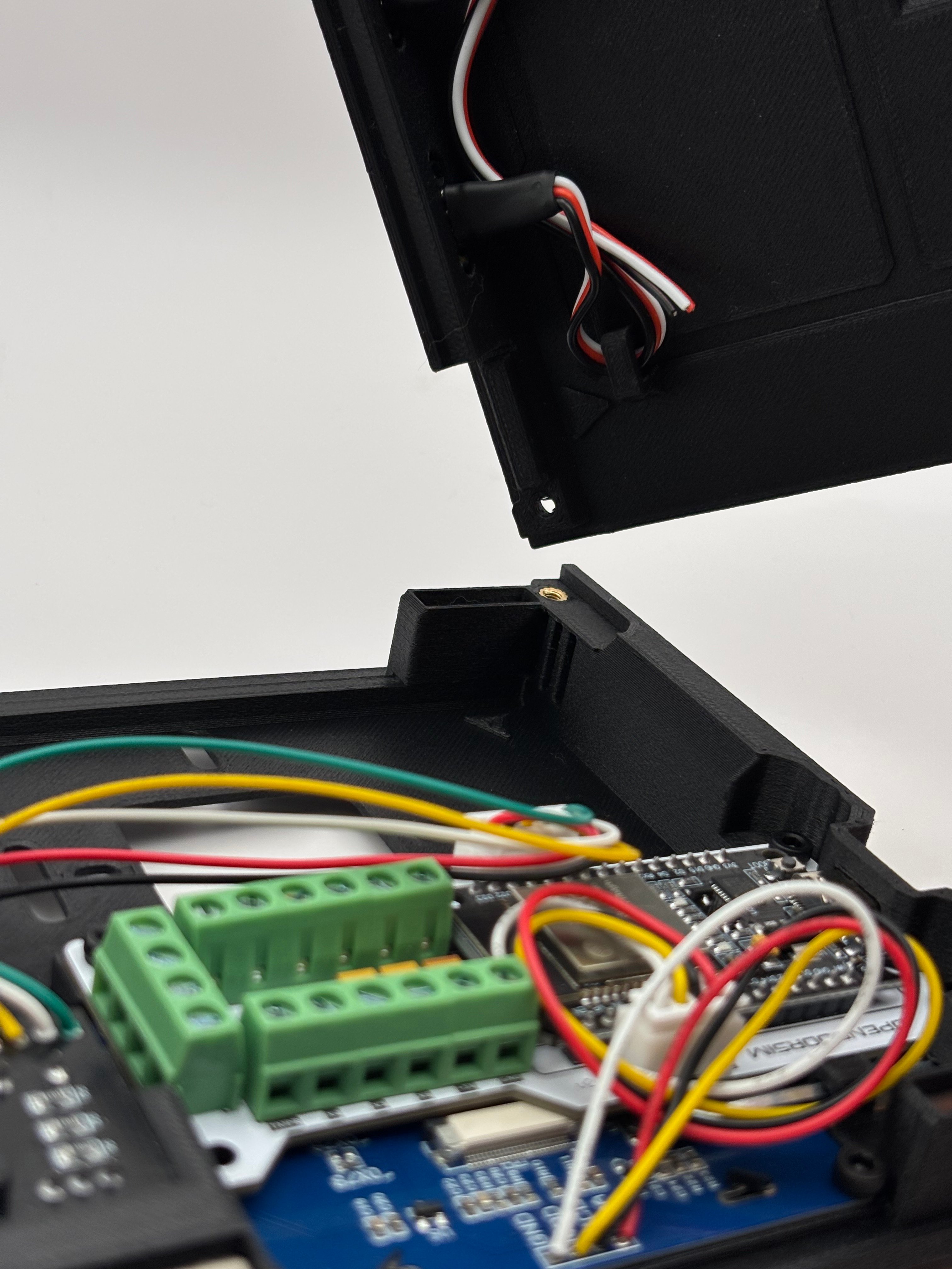
        Align triangles on the case body and lid and close gently but firmly. Although it is a tight fit, you should NOT have to force the case closed.

        <Danger>
          DO NOT FORCE CASE CLOSED. If the case is not closing, there is an alignment issue, or components that are blocking closure or blocking each other. Go back to previous steps, and look inside the case to find the issue and adjust. Once adjusted, the case should close.
        </Danger>

        <Columns cols={2}>
          <Column>
            <Frame>
              <img src="https://mintcdn.com/shortrangetechnologies/enV2q7ZuUn-OgOzW/images/IMG_6095.jpeg?fit=max&auto=format&n=enV2q7ZuUn-OgOzW&q=85&s=d482990ac676adfc1571abb67cab21aa" alt="IMG 6095" width="4032" height="3024" data-path="images/IMG_6095.jpeg" />
            </Frame>
          </Column>

          <Column>
            <Frame>
              <img src="https://mintcdn.com/shortrangetechnologies/enV2q7ZuUn-OgOzW/images/IMG_6094.jpeg?fit=max&auto=format&n=enV2q7ZuUn-OgOzW&q=85&s=0f3fc9b88a032c5e6696adca78fe1112" alt="IMG 6094" width="4032" height="3024" data-path="images/IMG_6094.jpeg" />
            </Frame>
          </Column>
        </Columns>

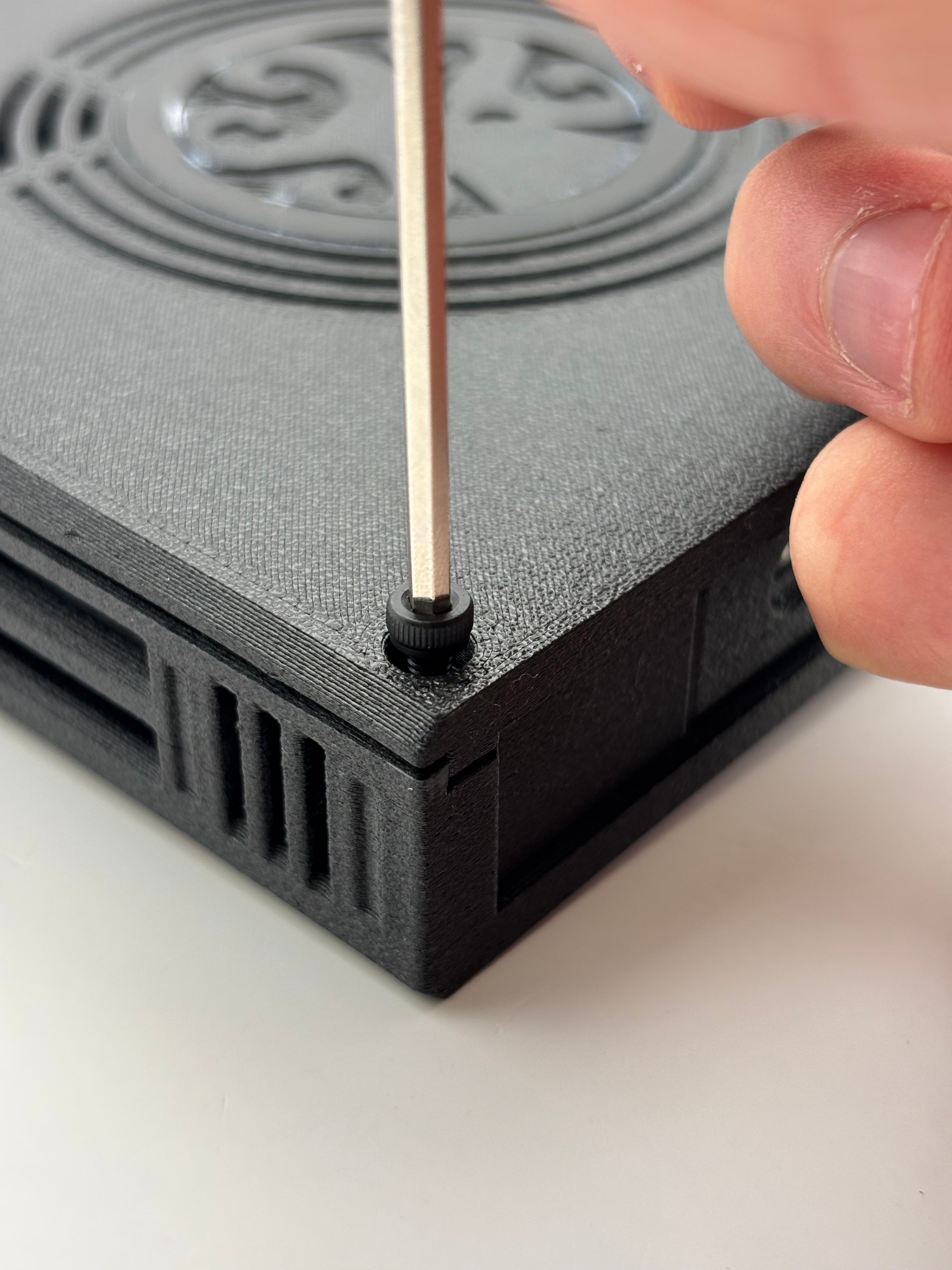
        Screw the case closed with the allen key (2.5mm) and the 4x long screws (M3x6).

        Slide the allen key into the storage slot when finished.
        <Columns cols={2}>
          <Column>
            <Frame>
              <img src="https://mintcdn.com/shortrangetechnologies/enV2q7ZuUn-OgOzW/images/IMG_6100-1.jpeg?fit=max&auto=format&n=enV2q7ZuUn-OgOzW&q=85&s=09c6ebffc189731395824dbce942db5a" alt="IMG 6100 1" width="4032" height="3024" data-path="images/IMG_6100-1.jpeg" />
            </Frame>
          </Column>

          <Column>
            <Frame>
              <img src="https://mintcdn.com/shortrangetechnologies/enV2q7ZuUn-OgOzW/images/IMG_6093.jpeg?fit=max&auto=format&n=enV2q7ZuUn-OgOzW&q=85&s=c19df2760a5a94c7a442c83c0cbbe215" alt="IMG 6093" width="4032" height="3024" data-path="images/IMG_6093.jpeg" />
            </Frame>
          </Column>
        </Columns>
      </Step>

      <Step title="Finish Up" titleSize="h3">
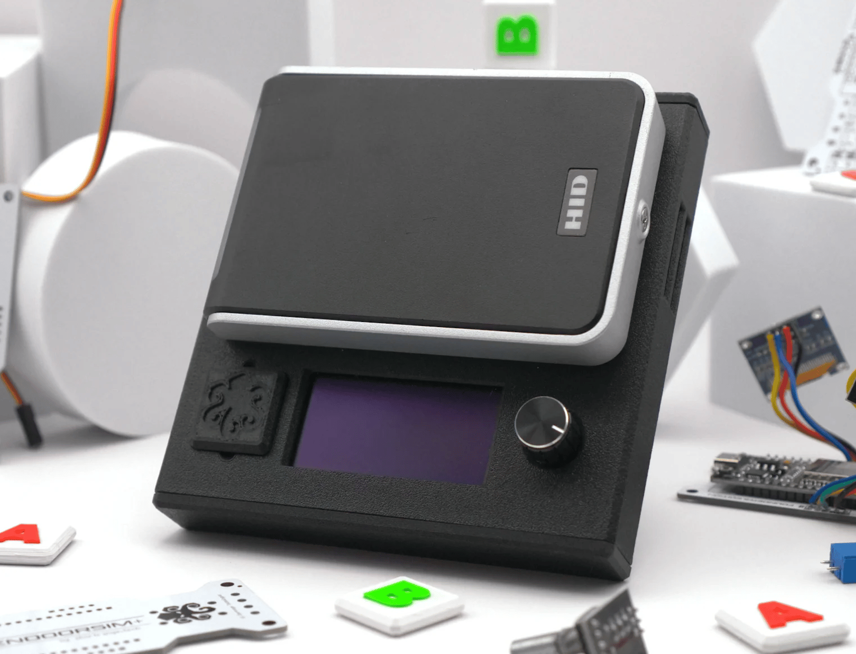
        Snap on the decal tile, and end caps... and you're done!
        <Frame>
          <img src="https://mintcdn.com/shortrangetechnologies/enV2q7ZuUn-OgOzW/images/Screenshot-2026-08-03-at-22.46.30.png?fit=max&auto=format&n=enV2q7ZuUn-OgOzW&q=85&s=9e8b335f2070aa4d6e716645ae0c2aa9" alt="Screenshot 2026 08 03 At 22 46 30" width="1700" height="1298" data-path="images/Screenshot-2026-08-03-at-22.46.30.png" />
        </Frame>
      </Step>
    </Steps>
  </Step>
</Steps>